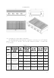
C-CR48-NG(LP) 4.2、Information of Gas Supply and Burner The minimum supplied gas pressure regulator is factory set at 4”Natural Gas W.C, and 10”L.P. Gas W.C. The external thread of product’s intake-tube is 3/4 inches.
Model #of burners and control method Gas Species C-CR24NG(LP) Natural 2 pieces Gas Independent control L.P. Gas C- CR 36-NG(L P) Natural 3 pieces Gas Independent control L.P. Gas C- CR 48-NG(L P) Natural 4 pieces Gas Independent control L.P. Gas Intake-tube pressure (in.W.5. Transport and Storage In the process of transportation, handle carefully and keep upright to prevent damage of the product packing. Wrapped equipment should not be in open air for a long time, and shall be placed in a well-ventilated and non-corrosive gases warehouse. When equipment needs temporary storage, rainproof measures should be taken. 6. Installation and Debugging Any erroneous installation, adjustment, refit, overhaul or maintenance may cause property damage or personal injury.
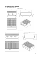
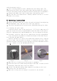
corners of the charbroiled bottom, ensure sufficient space for ventilation; Adjustable stainless steel legs to make the equipment level, and get the same level with other series of the same stove; Please lift the equipment rather than drag if you need to move it; Take away grate (Fig.12-18), take out bottom support, ensure fireshield (Fig12-20&21) under the bottom frame (Fig.12-17) without moving. Then symmetrically put vesuvianite (requirement: its diameter is about 3-5cm) on the bottom frame(Fig.
●Unplug pressure gauge after you accomplish pressure testing, then install needle type pressure joint screw arbor. Important: make sure screw up the needle valve to prevent gas escape! 6.2、Debugging It’s very important to debug the new stove. Through the comprehensive system test of equipment, we can ensure function and safety performance of products. Discovering any potential problems before use (such as equipment’s placement, ventilation, operation, etc), can avoid costly losses. 7.
provide warranty service; Steel cutting producers used to manufacture with sharp edges. The manufacturer has dealt with these sharp edges during production, however, we insist the operator take care when in contact with this piece of equipment; Always keep hands, hair and clothing away from heating source. Wait the unit cools down before cleaning. Because the unit is too hot to handle after using. 8.
8.3、Turn off the valve Revolve the control valve knob clockwise to "0" (Fig.2), so that extinguish flame of the main burner, but the pilot light still works. After turn off the equipment, the main fire should be stop more than 5 minutes before next using. 8.4、Stove Operation Before using the stove for the first time, please use a mild detergent to wipe it clean. Do not use corrosive or abrasives detergent.
intake. See 2 in P18. 8.6、Adjust air input Remove control panel, unscrew damper solid screw (Fig.10), revolve damper left to right (Fig.11), meanwhile, observe flame and adjust an appropriate opening degree. Then screw damper solid screw, make sure the equipment will not get loose in the process of moving and translation. Reinstall control panel. Caution: Each burner damper has been adjusted before delivery (once air input), normal use without adjustment but only switching gas.
authorized and licensed technicians; The product is made of 90% metals, and can not be discarded everywhere. Deal with it in accordance with the local codes. Instructions to clean appliance regularly with recommended cleaning agents, if necessary Recommended cleaning methods
Items Body Methods Times Wipe it with a soft cloth and mild detergent; daily Turn off valves when not in use; Control panel Wipe panel and control valve knob with mild detergent.10.Troubleshooting
Problems Not lighting Possible causes 1.Insufficient pressure in pipe gas 2.Nozzle occlusion 1.Insufficient pressure in pipe Ignite the pilot light but not the main fire 1.Contact the local gas supply dept. 2.Dredge nozzle gas 1.Contact the local gas supply dept. 2.The main fire nozzle occlusion 2.Dredge nozzle 3.Gas control valves have problems 3.Change gas control valves 4.The pilot light and the 4.Adjust the main fire’s distance is too distance of them far 5.11. Spare Parts The use of parts provided by other companies, our company has the right not to provide warranty service; Order replacement parts from authorized representatives and after-sale service agency. Provide the model no., serial no. and description when you order components. Fig.
Dimensions No. Matters Code Component name Qty Remark (mm)/Model 1 301110001 Adjustable steel legs 4 21105001001 2 21105002001 Catch tray 1 21105003001 φ41.5*100 C-CR24-NG(LP)\36 -NG(LP) \48-NG(LP) 507*620*26.5 C-CR24-NG(LP) 807*620*26.5 C-CR36-NG(LP) 1117*620*26.8 9 301060001 Needle type pressure joint 1 1/8"-27NPT C-CR24-NG(LP)\36NG(LP) \48-NG(LP) 301060002 Needle type pressure joint screw arbor 1 M5*23 C-CR24-NG(LP)\36NG(LP) \48-NG(LP) 2 10 11 12 13 14 15 301030002 301040006(NG) 301040007(LP) 301030001 21102001030 301170015 301060003 A18 stopcock A18 nozzle (NG) A18 nozzle(LP) Pilot light valve-single unit Air input pipe Pilot light head stator Pilot light head 3 C-CR24-NG(LP) A18-318 4 C-CR48-NG(LP) 2 C-CR24-NG(LP) 3 NG36 LP5
4 18 301020006 Grates 6 C-CR24-NG(LP) 150*525*22 8 21205001003 19 21205002003 Char grate back support brace 1 21205003003 C-CR48-NG(LP) L=600 C-CR24-NG(LP) L=900 C-CR36-NG(LP) L=1210 C-CR48-NG(LP) 2 20 21 22 23 24 301170004 301170003 301010007 Short covering fire board Long covering fire board U-type burner 301030014 pressure maintaining valve 301070001 24”countertop char broiler intake-tube 301070002 36”countertop char broiler intake-tube 301070003 48”countertop char broil
Model C-CR24-NG(LP) C-CR36-NG(LP) C-CR48-NG(LP) Adjustable counter top steel legs 4 pieces 4 pieces 4 pieces Catch tray 1 piece 1 piece 1 piece pressure maintaining valve 1 piece 1 piece 1 piece A18 Orifice 2 pieces 3 pieces 4 pieces instructions 1 piece 1 piece 1 piece Name Qty Notice: 1、Pressure maintaining valve connects with air intake, must be installed by authorized and licensed technicians, to ensure interface tightness. 2、Screw the hex nut (Fig.Intertek N IT E US LI S T E D SA C CM D CM A T I O N LI S T Conforms to ANSI STD Z83.11-2016 Certified to CSA STD 1.8-2016 Conforms to NSF/ANSI STD.4 Intertek 4003935 Our products have the advantages of good durability and low maintenance charge. But to update some components and necessary maintenance, can prolong life length of the products. Contact the dealer for assistance. In order to avoid confusion, please follow the format in figure 12 and table 4.