
Installation manual


3
Setting FIRST arm to operate as MASTER arm:
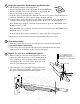
1. The MASTER arm should be at the fully retracted position
at this time.
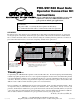
2. Set DIP switch #1:
OFF: pull to open
ON: push to open
3. Set DIP switch #2 and #3 (MODE 1 and MODE 2) to the desire sequence:
DIP #2 DIP #3 Dual Mode Sequence
OFF OFF Single gate mode.
ON OFF MASTER opens 1st, SLAVE opens 2 seconds later.
SLAVE closes 1st, MASTER closes 4 seconds later
OFF ON MASTER opens 1st, SLAVE opens 2 seconds later.
SLAVE closes 1st, MASTER closes 8 seconds later
ON ON MASTER and SLAVE simultaneously open and close.
4. DIP switch #4: (See main manual for additional details)
OFF: Pulse output at ‘AUX OUT’ terminal when gate is opening.
ON: Continuous output at ‘AUX OUT’ terminal when gate is moving.
Gate Operator in the
RERACTED POSITION
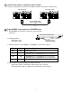
CONNECTING THE 45’ COMMUNICATION CABLE:
3
AUX
OUT
SOLAR
PA
NEL
18VAC
RCVR
GRN
BLK
RED
EXIT
SAFETY
EDGE
CYCLE
COMMON
LINK
AUX
OUT
SOLA
R
PA
NEL
18VAC
RCVR
GRN
BLK
RED
EXIT
SAFETY
EDGE
CYCLE
COMMON
LINK
45 Foot Communication
Cable run in PVC Conduit
First Gate Opener
Second Gate Opener
1. Plug the communication cable into the ‘LINK’ terminals of the opener control boards.
4