Installation Manual for the WARNING! This equipment is similar to other gate or door equipment and meets or exceeds Underwriters Laboratory Standard 325 (UL 325). However, gate equipment has hazards associated with its use and therefore by installing this product the installer and user accept full responsibility for following and noting the installation and safety instructions. Failure to follow installation and safety instructions can result in hazards developing due to improper assembly.
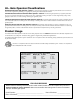
U.L. Gate Operator Classifications Residential Vehicular Gate Operator—Class I: A vehicular gate operator (or system) intended for use in a home of one-to-four single family dwelling, or a garage or parking area associated therewith.
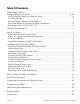
Table Of Contents Please Read This First....................................................................................................ii Important Safety Instructions................................................................................... iii–viii How to Manually Open and Close the Gate:............................................................... iii For the Consumer........................................................................................................
PLEASE READ THIS FIRST Thank you for purchasing a Rodeo Gear Medium Duty Gate Opener – a “do-it-yourself” automatic gate opener! When correctly installed and properly used, your Rodeo Gear Gate Opener will give you many years of reliable service. Please read the following information and watch the enclosed video to ensure you have the correct system for your particular needs. Furthermore, this manual and the video will enable you to properly install your Rodeo Gear Gate Opener.
IMPORTANT SAFETY INSTRUCTIONS Because automatic gate openers produce high levels of force, consumers need to know the potential hazards associated with improperly designed, installed, and maintained automated gate opener systems. Keep in mind that the gate opener is just one component of the total gate operating system. Each component must work in unison to provide the consumer with convenience, security, and safety. This manual contains various safety precautions and warnings for the consumer.
IMPORTANT SAFETY INSTRUCTIONS For The Consumer WARNING: To reduce the risk of injury or death: 1. READ AND FOLLOW ALL INSTRUCTIONS. Failure to meet the requirements set forth in the instruction manual could cause severe injury or death, for which the manufacturer cannot be held responsible. 2. When designing a system that will be entered from a highway or main thoroughfare, make sure the system is placed far enough from the road to prevent traffic congestion. 3.
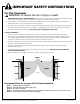
IMPORTANT SAFETY INSTRUCTIONS II. During Installation 1. Install the gate opener on the inside of the property and fence line. DO NOT install an opener on the outside of the gate where the public has access to it. 2. Be careful with moving parts and avoid close proximity to areas where fingers or hands could be pinched. 3. Devices such as contact sensors (safety edges) and non contact sensors (photo beams) provide additional protection against entrapment. 4.
IMPORTANT SAFETY INSTRUCTIONS 7. To operate this equipment safely, YOU must know how to disconnect the opener for manual gate operation (page iii). If you have read the instructions and still do not understand how to disconnect the opener, contact the Service Department. 8. Disconnect the opener ONLY when the power is TURNED OFF and the gate is NOT moving. 9. Make arrangements with local fire and law enforcement for emergency access. 10.
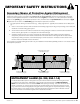
IMPORTANT SAFETY INSTRUCTIONS Secondary Means of Protection Against Entrapment As specified by Gate Opener Safety Standard, UL 325 (30A.1.1), automatic gate openers shall have an inherent entrapment sensing system, and shall have provisions for, or be supplied with, at least one independent secondary means to protect against entrapment. The Rodeo Gear utilizes Type A, an inherent (i.e., built-in) entrapment sensing system as the primary type of entrapment protection.
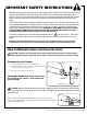
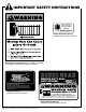
IMPORTANT SAFETY INSTRUCTIONS ! GTO DC SW202 Series Conforms to UL325 5th Edition Standards Serial No. XXXXXX MM362-0000000 Gates That Open, LLC - Tallahassee, Florida USA Product identification label (2) installed under rear mount of each arm Warning signs (4 enclosed) MUST be installed on both sides of each gate (3–5 feet above the bottom of the gate) www.mightymule.com 1-800-543-GATE (4283) MEDIUM DUTY DUAL L by... GATE OPENER TO MANUALLY OPEN AND CLOSE THE GATE 1. Turn opener power switch OFF.
Technical Specifications RODEO GEAR MEDIUM DUTY DUAL GATE OPENER _____________________________________ ______________________________________ DRIVE • Low friction screw drive (linear actuator) rated for -5 °F to +160 °F (-20 °C to +71 °C). • Powered by a 12 V motor with integral case hardened steel gear reducer. Motor speed reduced to 260 rpm. Generates 520 inch lb. of torque at 12 V. • Maximum opening arc of 110°.
Before You Begin 1. Determine Charging Options for Battery: Transformer OR Solar NEVER USE TRANSFORMER AND SOLAR PANEL(S) AT THE SAME TIME! It will damage the control board! IMPORTANT • The Rodeo Gear Medium Duty Dual is designed and intended for use with a 12 Volt automotive or lawn tractor battery. The battery must be placed inside a weatherproof case and located within 6' of the control box. The 8' battery harness connects the battery to the control board.
2. Check Direction of Gate Swing The Rodeo Gear is designed for PULL-TO-OPEN installations. PUSH-TO-OPEN installations require two Push-To-Open brackets [FM148]. Push-to-Open Installation Instructions begin on page 19. Your Property Your Property Push-To-Open Pull-To-Open (arm extends to open) (arm retracts to open) 3. Prepare the Gates • Gates must be plumb, level, and swing freely on their hinges. • Wheels must NOT be attached to the gates.
Parts List – Opener and Mounting Hardware ! WARNING Installation DVD (1) Battery Wire Harness (1) Transformer (1) RB502 Moving Gate Can Cause Injury Or Death 1. KEEP CLEAR! Gate may move at any time. 2. Do not allow children to operate gate or play in gate area. 3. This gate is for vehicles only. Pedestrians must use a separate entrance.
Tools and Materials Tools Needed: • Power Drill • Open End Wrenches — 1/2" and 9/16" • Adjustable Wrench • 3/8" Drill Bit • Hacksaw or Heavy Duty Bolt Cutters • Small Flat Bladed Screwdriver • Large Phillips Screwdriver • Tape Measure • Level • Wire Strippers • C-Clamps — small, medium, and large • Center Punch • Hammer (for center punch) • Extra person will be helpful Materials You May Need for the Installation: These items are NOT included with the g
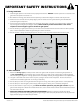
Installation Overview for Pull-To-Open Gates PUSH-TO-OPEN installation instructions begin on page 19. Example of an installation on a chain link fence: Control Box 120 Volt indoor Transformer Gate Swings Evenly and Freely Hung Firmly and Plumb First Opener Second Opener (surge protector not supplied) Gate Bracket Closed Position Stop Plates Run 1000' (max.) of low voltage wire to control box from transformer (wire not included).
Installation of the FIRST Gate Opener IMPORTANT: Determine which side of the driveway you will mount the control box. From this point on, the gate and gate opener on the same side as the control box will be referred to as the FIRST gate and gate opener. The gate and gate opener on the opposite side of the driveway from the control box will be referred to as the SECOND gate and gate opener.
Step 1 Insert the 3/8" x 11/2" bolt through the center hole of the post brackets and post pivot bracket. Secure with a 3/8" washer and 3/8" lock nut. DO NOT overtighten the lock nut (the post pivot bracket will have to be adjusted later). Step 2 Attach post bracket assembly to the rear mount of the opener with a clevis pin and a 3/8" washer. Secure the clevis pin with a hairpin clip.
Step 5 Gate in the CLOSED POSITION 1" minimum Be sure the position of the gate opener and brackets allows for 1" of clearance between the gate and the opener in both the open and closed position, while at the same time maintaining a maximum distance of 13" from the end of the retracted opener arm to the gate bracket with the gate in the closed position.
Step 9 Drill 3/8" holes through post as marked. Fasten post bracket assembly to the fence post using two 3/8" x 8" bolts, washers and lock nuts. You EXAMPLES TOP VIEW Gate Bracket Mounting Examples must use bolts that completely penetrate the post. Round Metal Post Step 10 Drill 3/8" holes through the gate cross member as marked. Mount gate bracket using two 3/8" x 2 3/4" bolts, washers, and lock nuts.
Install the Closed Position Stop Plates The closed position stop plate is attached to the FIRST gate to help stabilize the gate leaf in the closed position. An optional low profile ground stop, when used with the closed position stop plate, provides a secure point for the SECOND gate to close against. To further enhance the stability and security of your gate, install a Mighty Mule Automatic Gate Lock [FM143] page 26).
Step 4 Mount Vertically Using appropriate hardware for your type of gate, attach the vertical closed position stop plate to the SECOND gate frame at the point where it will come in contact with the low profile ground stop. Do not tighten it completely at this time. You must slide the closed position stop plate toward the low profile ground stop until they touch. Once you have moved the stop plate to the correct position, tighten its hardware completely.
Connect Opener Power Cables Step 1 Bring FIRST power cable into the control box through a strain relief slot, leaving enough wire to reach the FIRST OPR. terminal block. STATUS 1st OPR. OPEN < JOG > CLOSE 2nd OPR. Insert the individual power cable wires into appropriate terminals on the FIRST OPR. terminal block (white to WHT; green to GRN; red to RED; black to BLK). Tighten the set screws. MIN MAX OFF STALL FORCE SET LIMIT PWR. 120 SEC. AUTO CLOSE REMOVE JUMPER FOR PUSH TO OPEN OPTION SFTY.
Control Box Step 3 Lay the measured length of low voltage wire in a trench following a path from the selected electrical outlet to the control box. Wires coming up from the ground should be run through PVC conduit to protect them from lawn mower blades, weed eaters, and grazing animals. Be sure to bury the wire laid in the trench. First Gate Opener 120 Volt indoor Transformer (surge protector not supplied) 12 Volt automotive or marine type battery in weather proof housing (not included).
Step 6 At the AC outlet, strip 1/2" of insulation from the ends of the low voltage wire. Attach these stripped ends to the transformer terminals. We suggest adding crimp on fork lugs to the end of each wire before attaching it to the transformer. Make sure the exposed wires do not touch each other! Connect Battery Harness to Control Board Step 1 Make sure control box is OFF. Locate the BATTERY wires from the CONTROL BOARD marked BATT + and BATT –.
case within 6 feet of where the control box is mounted. Control Box First Gate Opener With-in 6 feet Battery Cable from Control Box 12 Volt automotive or marine type battery in weather proof housing (not included). 20 BLACK to NEGATIVE RED to POSITIVE Step 2 Attach the battery wires provided to the terminals of the battery. Take care to attach the BLACK wire to the NEGATIVE terminal and the RED wire to the POSITIVE terminal. Reverse connection will cause damage to the control board.
Step 3 Press and HOLD the 1st Opener CLOSE button on the control board and be prepared to RELEASE the button when the gate reaches the desired closed position/limit. Use the JOG OPEN and CLOSE buttons to "fine tune" the gate position if neccessary. FIRST Opener JOG Buttons STATUS 1st OPR. OPEN < JOG > CLOSE SECOND Opener JOG Buttons 2nd OPR. MIN PWR. 120 SEC.
Personalize Your Transmitter Setting All GTO transmitters have a standard setting and are ready to operate your Rodeo Gear Gate Opener. For your safety and security, we strongly recommend that you replace the factory setting with your own personal setting. NOTE: If you have multiple transmitters, you should adjust all of them at this time. LE Step 1 D Use a small phillips head screw driver to remove the transmitter cover.
Push-To-Open Installation Instructions PUSH-TO-OPEN gates open out from the property (opener arms extend to open). Push-To-Open Brackets are required for this type of installation, one for each gate [FM148] page 26).). In a Push-To-Open installation, the opener is installed while the gate is in the closed position and the opener fully retracted. Swinging gates MUST NEVER open into public access areas! Step 1: Read "Installation of the Gate Opener" on page 7.
Step 3: Attach Opener Arm (page 10) Step 4: Install Closed Position Stop Plates (page 11) Step 5: Mount the Control Box (page 12) Step 6: Connect Opener Power Cables (page 13) Step 7: Connect the Transformer (page 13) OR Solar Charger (page 21) Step 8: Connect Battery Harness (page 15) Step 9: Connect Battery (page 16) Step 10: Remove Push-To-Open Jumper STATUS A. Make sure the control box power switch is OFF. B. Use small pliers to move the JUMPER for PUSH-TO-OPEN applications. 1st OPR.
Solar Panel Instructions NEVER USE TRANSFORMER AND SOLAR PANEL(S) AT THE SAME TIME! It will damage the control board! IMPORTANT INFORMATION ABOUT LOW VOLTAGE WIRE: • The only wire acceptable for use with Mighty Mule products is 16 gauge stranded, low voltage, PVC sheathed wire. This particular gauge enables the solar panel to provide an adequate charge through the control board to the battery at distances up to 250'. • DO NOT use telephone wire or solid core wire.
Connecting Accessories and Safety Devices Although Mighty Mule strongly recommends the use of additional safety devices, we do not endorse any specific brands. Only use products that are certified and listed to be in compliance with any applicable UL standards (Underwriters Laboratories) and national and regional safety codes. Call Mighty Mule Sales at 1-800-543-4283 for information on compatible products for your specific application.
STATUS 1st OPR. OPEN < JOG > CLOSE 2nd OPR. PWR. SET LIMIT • Activation of this input while the gate is closing will cause the gate to stop and return to the opened position. 1 SFTY. 2 EXIT • Activation of this input while the gate is opening has no effect. (gate will continue to open) 3 CYCLE • Activation of this input while gate is idle will prevent gate from closing.
Troubleshooting Guide If your gate opener does not function properly, use this guide or use the online troubleshooter at http://support.gtoinc.com before calling the Service Department. VISUAL AND AUDIBLE DIAGNOSTIC INDICATORS 1. Visual Indicators: a. Power LED (Green): • ON: AC power or Solar power is present. • OFF: There is no input power. b.
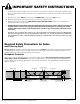
VOLTAGE RATINGS 14 Vac Transformer______________ 10.0 to 16.0 Vac 10 W Solar panel ________________ 18.0 to 22.0 Vdc 600 mA Measure voltage at panel and control box. 12 V Battery_____________________ 12.5 to 13.5 Vdc Charging circuit _________________ 13.8 to 14.8 Vdc Measure voltage at battery terminals with battery connected Gate and Opener Maintenance: 1. Keep gates properly maintained. Grease hinges. Make sure gates remain level. Replace worn or damagedhardware.
Accessories ACCESS CONTROLS Please call your retailler, or visit www.mightymule.com for photos and detailed descriptions of Accessories. Or call 1-800-543-GATE (4283). Solar Panel (FM123) 10 watt If your gate is more than 1000' from an AC power source, you can choose to maintain the battery charge with the Solar Panel Charging Kit. Installation in some regions of the world will require multiple solar panels for adequate charging power.