
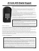
Installation Manual
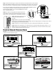
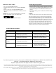

Step 2: To hard-wire the keypad - strip the wires back 3/16” and attach the wires to the terminal
block marked RELAY OUTPUT on the keypad control board as shown to the right. Connect the
other end to the opener’s control board as shown in Control Board Connections section below.
To wire the power supply to the keypad attach the wires to the AC/DC POWER IN terminal
on the keypad control board as shown to the right. Connect the other
end to the opener’s battery - one end to the POSITIVE pole and the
other to the NEGATIVE pole.
NOTE: For a hard-wired application the jumper between the
two terminals on the keypad control board must be connected
(ON) as shown. This will disable the 318 MHz RF transmitter.
Step 3: Slide the keypad into the cover
and secure with the small screws
provided.
Step 4: With the power to the opener turned OFF.
Remove opener control board cover and feed enough of the low voltage keypad wire through a strain relief to
reach the gate opener control board terminals.
Step 5: Attach the wires from the keypad to the opener control board terminal blocks as shown below.
Step 6: Replace the control board cover and turn the power switch ON. Test the keypad by entering 1 2 3 4.
Step 7: Program your ‘Personal Master Code’ and any additional entry codes (for a total of 25 entry codes)
you wish. See Programming the Keypad section.
RELAY
OUTPUT
AC
/DC
POWER IN
1 2 3 4 5 6 7 8 9
+
0
–
Jumper ON
Jumper OFF
Hard-wire from Gate Opener
Po
wer Supply from
Opener Battery
#
1
#
2
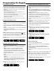
Control Board Connections
1
2
ABC
3
DEF
4
GHI
5
JKL
6
MNO
7
PRS
8
TUV
9
WXY
0
EDGE
RED
BLK
GREEN
SAFETY
CYCLE
RADIO
18 VAC
INPUT
LEARN
TRANSMITTER
SET
CLOSE
LIMIT
COMMON
15 AMP
Connect #1 wire from the
RELAY OUTPUT terminals on
the keypad to CYCLE terminal on
the gate opener control board.
Connect #2 wire from the
RELAY OUTPUT terminals on
the keypad to the COMMON
terminal on the gate opener
control board.
Mighty Mule 250 E-Z Gate Opener
Control Board
#1
#2
GRN
BLK
RED
RECEIVER
COM COM
C
Y
C
LE
C
L
OSE
CYCLE
CLOSE
SAFETY
EXIT
OPEN
SHADOW
LOOP
CLOSE
EDGE
OPEN
EDGE
J
11
J11
J8
J12
GTO/PRO DC Powered PRO-SW3000
and PRO-SW4000 Control Boards
Connect #1 wire from the
RELAY OUTPUT terminals on
the keypad to CYCLE terminal on
the gate opener control board.
Connect #2 wire from
the RELAY OUTPUT
terminals on the keypad
to the COM terminal on
the gate opener control
board.
#1
#2
NOTE: If your control board doesn’t look like any of these diagrams, please call GTO Technical Service at 1-800-543-1236
or 850-575-4144 for additional support.
RECR
GRN
BLK
RED
EXIT
SAFETY
EDGE
CYCLE
COMMON
LINK
Mighty Mule 350 Control Board
Connect #1 wire from the
RELAY OUTPUT terminals
on the keypad to CYCLE
terminal on the gate opener
control board.
Connect #2 wire from the RELAY
OUTPUT terminals on the keypad
to the COMMMON terminal on
the gate opener control board.
#1
#2
+
–
G
R
B
GTO
RCVR.
CLOSE
OPE
N
FIRE DEPT
.
SHAD
. LOOP
SAFE LOOP
ENTRY LOOP
FREE EXIT
CYCL
E
COMMON
COMMON
COMMON
COMMON
AU
X 2
ACCES. PWR
24VDC
TB8
TB7
TB6
TB5
TB4
TB3
GTO/PRO AC Powered Operator Control Board
Connect #1 wire from the
RELAY OUTPUT terminals on
the keypad to CYCLE terminal on
the gate opener control board.
Connect #2 wire from the
RELAY OUTPUT terminals
on the keypad to the
COMMON terminal on the
gate opener control board.
#1
#2
RECEIVER
COM COM
CYCLE
CLOSE
SAFETY
EXIT/
OPEN
SHADOW
LOOP
CLOSE
EDGE
OPEN
EDGE
BLKGRN RED
Mighty Mule 500 & 502
Control Boards
Connect #1 wire from the
RELAY OUTPUT terminals on
the keypad to CYCLE terminal on
the gate opener control board.
Connect #2 wire from
the RELAY OUTPUT
terminals on the keypad
to the COM terminal on
the gate opener control
board.
#1
#2