IMPORTANT: Before you install the automatic gate lock be sure your gate is level, moves freely on its hinges, and does not bind or drag against the ground. AUTOMATIC GATE LOCK ® Installation Manual PLEASE NOTE: Because of the various mounting applications, no mounting hardware is provided with the GTO Automatic Gate Lock. All necessary mounting hardware can be obtained from your local hardware store; all other hardware is provided.
Before You Start... For the GTO Automatic Gate Lock to work properly, the gate must close firmly and engage the lock catch against the lock receiver. Achieving optimal closure may require slight adjustments to the gate opener settings. Installing the lock with the Mighty Mule® E-Z Gate® Opener may require slight movement of the stroke adjustment and changes to the obstruction sensitivity. See Setting the Gate Closed Position in your Mighty Mule Installation Manual for information on these adjustments.
Installing The Gate Lock NOTE: The Automatic Gate Lock can be installed on single and dual gate systems. Use the appropiate instructions for the system you have - SINGLE GATE (below) or DUAL GATES (page 4). Single Gate Installation Disconnect gate opener by removing hairpin clip and clevis pin from the gate bracket end of the opener. Disconnecting the opener will allow the gate to swing freely during installation of the gate lock.
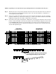
Illustration B Iron or Aluminum Tube Fence and Gate Installation Remember to check the alignment and mark positions before drilling holes in fence post and gate. Clevis Pin GTO Automatic Gate Lock Receiver Locking Cap Carriage bolts, washers, and nuts (not provided; size of fasteners depends on the gate) Illustration D Illustration C Chain Link Fence and Gate Installation Remember to check the alignment and mark positions before drilling holes in fence post .
Dual Gate Installation Disconnect gate openers by removing hairpin clip and clevis pin from the gate bracket end of the openers. Disconnecting the openers will allow the gates to swing freely during installation of the gate lock. NOTE: In a DUAL GATE INSTALLATION the gate opener on the same side of the driveway as the control box is known as the MASTER GATE OPENER and that gate is refered to as the MASTER GATE.
With the sequencing set correctly follow the steps and diagrams below to mount the lock to the gates. Step 1: With the gate in the closed position, determine the best location for the lock and lock receiver. The lock and receiver must be level and aligned with the opener. Also, the lock should have a solid surface or cross member to provide stability.
Illustration E Remember to check the alignment and mark positions before drilling holes in fence post and gate. Clevis Pin GTO Automatic Gate Lock Receiver Locking Cap Carriage bolts, washers, and nuts (not provided; size of fasteners depends on the gate) Illustration G Illustration F Remember to check the alignment and mark positions before drilling holes in fence post .
Connecting the Lock to the Opener Control Board: IMPORTANT: All Mighty Mule® and GTO/PRO® gate opener control boards manufactured since March 2000, have terminal strip wire connections (see Illustration H). If your gate opener doesn't have terminal strip connectors, you will need to follow the instructions for "Wiring the Lock to Pre-March 2000 Gate Opener Control Boards".
NOTE: If the gate opens away from the property (push-to-open) place the RED wire from the opener power cable inside the “through” channel on the Wire Connector. Crimp the Wire Connector closed with pliers and fold plastic locking tab into place until it locks shut. If this is a dual gate installation, use the RED (push-to-open) or BLACK (pull-to-open) wire from the MASTER GATE OPENER that extends from the power cable to the opener. Step 5.
Wiring the Lock to Gate Opener Control Boards with Terminal Strips Step 1. Turn control box power switch OFF and unplug the transformer or disconnect the solar panel. Remove control box cover and disconnect battery lead wires from the battery terminals before wiring the lock board to the opener control board. Step 2. Connect the WHITE wire (included) to Terminal #1 on the lock board. Connect the RED battery lead wire (included) to Terminal #5 on the lock board.
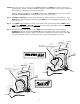
Wiring the Lock to Mighty Mule FM-700/702 and GTO/PRO 1000 and 2000 Gate Opener Control Boards with Terminal Strips 12 Volt Battery Double Spade Tongue Connectors OS AUTO60CL + – BATT 120 OFF INERTIA RE D OBSTR. SENS. BLACK POW ER IN M ALAR MAX MAX MIN LEARN B R G BLU WHT ORG GRN OPN EDG CLS EDG ORG BLU GRN BLK RED OPN EDG CLS EDG ORG BLU GRN BLK RED OR ERAT ND OP Opener Control Board (Generation 2000) MIN SH PULL/PU AL SGNL/DU 1 SEQ SEQ2 SOLAR 18VAC – + ~ ~ E STATUS .
Wiring the Lock to Mighty Mule 500/502 and GTO/PRO SW-3000 and SW-4000 Gate Opener Control Boards 500/502 and 3000/4000 Control Board STALL FORCE SWITCH OPEN EDGE CLOSE EDGE SHADOW LOOP EXIT/ OPEN COM COM SAFETY BLK RE D RED BLK ORG BRN BLUE GRN WHT BRN ORG MASTER INPUTS CYCLE CLOSE MIN MAX GRN WHT BLUE GRN BLK RED RECEIVER Lock Board Double Spade Connector WHITE Wire to RED Master Terminal for Pull-To-Open gates or BLK for Push-To-Open MASTER OPENER POWER CABLE BLACK Wire To Bat
IMPORTANT: For the optimum service and safety, find the ideal obstruction sensing setting for your gate opener. Depending on the weight of your gate, the ideal setting will be just enough to move your gate without self-obstruction (stopping or reversing due to its own weight), yet sensitive enough to reverse and stop when it meets with an obstruction such as a car or animal. See the GTO Installation Manual for information on obstruction settings.