
Installation Guide


31
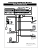
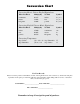
1 COM: Circuit common (reference for all logic input)
•Two(2)terminalstoprovideextracommonconnectionpoint.
2 CYCLE: (Typically for use with doorbell button or hardwired key pad)
• Eachactivationatthisinputwillcycletheoperationasfollows:
…. OPEN STOP CLOSE STOP OPEN …
3 SAFETY: (Typically for use with photo beam device, loop detector
or other non-contact sensors)
• Activationofthisinputwhilethegateisclosingwillcausethegateto
stop and return to the opened position.
• Activationofthisinputwhilethegateisopeninghasnoeffect(gate
will continue to open).
• Activationofthisinputwhilegateisidlewillpreventgatefromclosing.
4 EXIT: (Typically for use with exit loop or wand)
• Activationofthisinputwillopenthegateifit’snotalreadyatthe
open position
• Activationofthisinputwhileatopenlimitwillrestarttheautoclosetime
(if enabled).
5 SHADOW: (Typically for use with loop detector device)
• Thisinputisonlymonitoredwhenthegateisatthefullyopen
position. At any other position, activation of this input has no effect on
gate operation.
• Activationofthisinputwhilegateatthefullyopenpositionwill
prevent gate from closing.
6 CLOSE EDGE: (Typically for use with safety edge device)
• Activationofthisinputwhilethegateisclosingwillcausethegateto
stop and reverse direction for approximately 2 seconds.
• Activationofthisinputwhilethegateisopeninghasnoeffect(gatewillcontinuetoopen).
• Activationofthisinputwhilegateisidlewillpreventgatefromclosing.
7 OPEN EDGE: (Typically for use with safety edge device)
• Activationofthisinputwhilethegateisopeningwillcausethegateto
stop and reverse direction for approximately 2 seconds.
• Activationofthisinputwhilethegateisclosinghasnoeffect(gate
will continue to close).
• Activationofthisinputwhilegateisidlewillpreventgatefromopening.
1
2
3
4
7
5
6
BATT-
1 2 3 4
ON
RECEIVER
LEARN
MAST LIMIT
LEARN
SLV LIMIT
S3
S4
ALM
S2
OFF
SOFT START OFF
WARNING OFF
OPEN PULL
SLV OPEN DLY.
MODE1 OFF
MODE2 OFF
ON
ON
PUSH
SIMULT.
ON
ON
120 MIN MAX
CHARGING
PWR IN
GTO RCVR.
WHT
BLU
BRN
ORG
RED
BLK
GRN
WHT
BLU
BRN
ORG
RED
BLK
GRN
COM
GRN
BLK
RED
CYCLE
SAFETY
EXIT
SHADOW
OPEN
EDGE
COM
LOCK
PWR
AUX
RLY
POWER
INPUTS
CONTROL
INPUTS
MASTER CABLESLAVE CABLE
CONTROL INPUTS
CLOSE
EDGE
GTO
LOCK
AUX
1 2 3 4 5 6 7
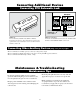
NOTE:
• Allcontrolinputsaredry-contact,normallyopen,inputs.DONOTapplyexternalvoltagesourcestotheseinputs.
• AllinputsareconnectedwithrespecttoCOMMON terminal.
• Thestatuslightwillblinkoncewhenitscorrespondinginputisactivated.
Input Connections
Connecting Additional Devices