Installation Manual for the MM-LPS13 Slide Gate Operator System PROFESSIONAL INSTALLATION RECOMMENDED! WARNING! This equipment is similar to other gate or door equipment and meets or exceeds Underwriters Laboratory Standard 325 (UL 325). However, gate equipment has hazards associated with its use and therefore by installing this product the installer and user accept full responsibility for following and noting the installation and safety instructions.
CLASS RATING Class Rating The Mighty Mule MM-LPS13 Gate Operator is intended for use with vehicular slide gates in single family residential applications. The operator is system certified to be in compliance with UL 325, current edition, as of publication date. Vehicular Gate Operator Class Categories: Residential Vehicular Gate Operator—Class I: A vehicular gate operator (or system) intended for use in a home of one-to-four single family dwellings, or a garage or parking area associated therewith.
Table Of Contents Class Rating ���������������������������������������������������������������������������������������������������������������������������������������� Inside Cover Please Read This First ����������������������������������������������������������������������������������������������������������������������������������������������i Important Safety Instructions �����������������������������������������������������������������������������������������������������������������������������ii Before
PLEASE READ THIS FIRST Thank you for purchasing a Mighty Mule MM-LPS13. When correctly installed and properly used, your MM-LPS13 operator will give you many years of reliable service. Please read the following information to ensure you have the correct system for your particular needs. This manual will enable you to properly install your MM-LPS13 Automatic Gate Operator. The MM-LPS13 operator is designed for installation on a slide-to-open single leaf gate.
IMPORTANT SAFETY INSTRUCTIONS IMPORTANT SAFETY INSTRUCTIONS Because automatic gate operators produce high levels of force, consumers need to know the potential hazards associated with improperly designed, installed, and maintained automated gate operator systems. Keep in mind that the gate operator is just one component of the total gate operating system. Each component must work in unison to provide the consumer with convenience, security, and safety.
IMPORTANT SAFETY INSTRUCTIONS For The Consumer WARNING: To reduce the risk of injury or death: 1. READ AND FOLLOW ALL INSTRUCTIONS. Failure to meet the requirements set forth in the instruction manual could cause severe injury or death, for which the manufacturer cannot be held responsible. 2. When designing a system that will be entered from a highway or main thoroughfare, make sure the system is placed far enough from the road to prevent traffic congestion. 3.
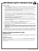
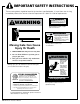
IMPORTANT SAFETY INSTRUCTIONS III. After Installation 1. Attach the warning signs (included) to each side of the gate to alert the public of automatic gate operation. It is your responsibility to post warning signs on both sides of your gate. If any of these signs or warning decals become damaged, illegible or missing, replace them immediately. Contact GTO for free replacements. 2. The gate is automatic and could move at any time, posing a serious risk of entrapment.
IMPORTANT SAFETY INSTRUCTIONS Secondary Means of Protection Against Entrapment As specified by Gate Operator Safety Standard, UL 325 (30A.1.1), automatic gate operators shall have an inherent entrapment sensing system, and shall have provisions for, or be supplied with, at least one independent secondary means to protect against entrapment. The MM-LPS13 utilizes Type A, an inherent (i.e., built-in) entrapment sensing system as the primary type of entrapment protection.
IMPORTANT SAFETY INSTRUCTIONS Required SafetyGate Precautions for Gates Install Screen Guard Over and Fence Injuries may occur when people place their hands, arms, legs, etc., through openings in the gate grill when the gate is operated, trapping them between the grill and the fence post (or fence). All openings of a horizontal slide gate must be guarded or screened to prevent a 2 ¼” diameter sphere from passing through openings anywhere in the gate.
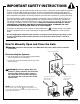
IMPORTANT SAFETY INSTRUCTIONS These warning labels should be found at the locations specified below. If any of them are missing, immediately contact the Technical Service Department at 1-800-543-1236 for replacements. ! ! WARNING WARNING • Adjusting limit switches with power on will activate gate. • Injury may result if fingers get caught under switch plate while adjusting switches. • Use extreme caution when adjusting switches. Warning label located on right side of control box.
BEFORE YOU BEGIN... 1. Determine Charging Option for Battery: Transformer OR Solar NEVER USE TRANSFORMER AND SOLAR PANEL(S) AT THE SAME TIME. It will damage the control board. IMPORTANT: • The MM-LPS13 12 volt battery [FM150] must be charged by either connecting the transformer (included) or solar panel kit [FM123] to the control board. • The transformer is designed for indoor use.
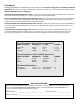
MM-LPS13 TECHNICAL SPECIFICATIONS DRIVE • Powered by a 1/4 hp 12 V motor with integral case hardened steel gear reducer. Motor speed reduced to 90 rpm. • Gate velocity: 1 ft/second. POWER • Two blade style fuses rated for 20 A. NOTE: The transformer or the solar panel should not be connected directly to any battery. Transformer must be connected to the control board with a minimum of 16 gauge, stranded, dual conductor, direct burial low voltage wire.
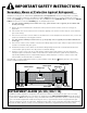
MM-LPS13 PARTS IDENTIFICATION Control Box with Control Board Operator Operator Housing (R4966) ALIGN THIS EDGE WITH EDGE OF CONCRETE PAD CLOSEST TO GATE STRING ANCHOR BOLT LOCATION ANCHOR BOLT LOCATION OUTLINE OF OPERATOR CONCRETE OUTLINE/ INSIDE EDGE OF FORM CONCRETE OUTLINE/ INSIDE EDGE OF FORM (1) 12 Volt 7 amp Battery (FM150) (2) Chain Brackets (204IH) 18 Vac Transformer 120 Volt (RB570) ANCHOR BOLT LOCATION ANCHOR BOLT LOCATION MOUNTING TEMPLATE Receiver (RB709U-NB) Transmitter (FM135)
TOOLS AND MATERIALS Tools Needed: • Hammer Drill • 3/ ” Masonry 8 • Open End Wrenches • Adjustable Wrench • String & String Level • Chain Break or Punch • Plumb Bob • Hacksaw or Heavy Duty Bolt Cutters • Small Flat Bladed Screwdriver • Large Phillips Screwdriver • Tape Measure • Level • Wire Strippers • C-Clamps — small, medium, and large • Center Punch • Extra person will be helpful Drill Bit Materials You May Need for the Installation: These items are NOT included with the
GATE OPERATOR INSTALLATION Gate Preparation Be sure the gate is properly installed and slides smoothly before installing the MM-LPS13 Slide Gate Operator. The gate must be plumb, level, and move freely. The gate must not bind or drag on the ground. Never use a wheel on the gate, because the additional drag and resistance can cause the operator to obstruct.
DETERMINING MOUNTING OPTIONS Concrete Pad Operator should be mounted securely on a level concrete pad. If you do not have an existing pad to work with, be sure to to install wiring conduit before pouring concrete. You must use four ³/₈” diameter mounting anchors, washers and nuts (not included) to mount the operator to the pad. Use mounting template provided (see page 9). Operator New Pad Check local building codes for concrete pad depth below ground level.
DETERMINING OPERATOR MOUNT POSITION Step 1 Be sure the gate is properly installed and slides smoothly before installing the MM-LPS13 . The gate must be plumb, level, and move freely. The gate must not bind or drag on the ground. Never use a wheel on the gate, because the additional drag and resistance can cause the operator to obstruct. Level Level Plumb Plumb Concrete Concrete Concrete Concrete Step 2 Install chain brackets at each end of the gate on the inside (operator side) of the gate.
Step 3 Adjust brackets as necessary until string is level and 7” minimum above the ground (see Illustration A). (Use a string level as shown). Tighten both brackets using wrench. String String Level String Step 4 Find the center between the two roller/gate support posts. This should coincide with the position of the center point of the MMLPS13 operator. Pad depth (minimum of 18” below ground) is dependent on soil conditions and local code (please check your local code).
USING THE MOUNTING TEMPLATE String Mounting Template Mounting String Template Mounting Template Mounting Template Align these lines with edges of concrete pad Align these lines with edges of concrete pad String String Align this edge of mounting template Align this edge of with inside edge of mounting template wood form with inside edge of wood form Wood form for concrete pad Wood form for concrete pad String GATE GATE String Align this edge of mounting template Align this edge of with this edge
DETERMINING THE CHAIN LENGTH Attach chain to the quick release pins and install pins in the chain bracket slot farthest from the gate. Chain Bracket Quick Release Pin Step 1 After opener is secured, remove the string from the quick release pins. Attach the chain to one quick release pin with a master link (see Illustration). Run the chain through the chain sprocket and idler wheels. (see Illustration). Step 2 Chain Master Link Pull the chain to the second chain bracket. (see Illustration).
POWERING THE SYSTEM OFF Connecting the Battery position Step 1 Make sure the control box power switch is in the OFF position. Slide battery into position with its terminals to the left. Connect the black battery lead to the negative (–) terminal, and the red battery lead to the positive (+) terminal.
Step 4 Strip the ends of the low voltage wire and attach ends to the transformer terminals. Step 5 . PWR. SW – BATT + SURGE PROTECTOR Transformer To prevent damage to transformer, make sure the exposed wire ends do not touch each other! STATUS Plug the transformer into a weatherproof electrical outlet. NOTE: Use of a surge protector is strongly recommended. PWR. R IN SW. POWE INERTIA Red (+) Black (–) MAX UCT OBSTRS.
DETERMINING THE GATE’S OPEN POSITION Verify that the chain is completely removed from operator and both chain brackets at this time.. W PWR. S – Step 1 — Turn the control box power switch +to Bthe ATT ON position. Step 2 — Install a jumper wire. Wire one end of the jumper wire to the ! WARNING Moving Gate Can Cause Injury Or Death STATUS 1. KEEP CLEAR! Gate may move at any time. 2. Do not allow children to operate gate or play in gate area. 3. This gate is for vehicles only.
ADJUSTING THE LIMIT SWITCHES The limit switches determine how far the gate travels to open and to close. BEFORE Adjusting the limit switches, make sure that the control box power switch is OFF. NOTE - Turn operator power switch to the OFF position before adjusting the limit switches. Limit Nut A Adjust the limit switches using the limit nuts. Lift limit switch plate to adjust limit nuts (see Illustration).
ADJUSTING THE POTENTIOMETERS WARNING! All three potentiometers were set to minimum at the factory. The OBSTRUCT SENS. potentiometer MUST be adjusted above the factory setting for your MM-LPS13 operator to function properly. If the potentiometer is left at MIN, your gate operator may “obstruct” (i.e., stop and reverse) as soon as it is activated. BE SURE TO PROPERLY RETEST THE GATE OPERATOR AFTER MAKING ANY ADJUSTMENTS; FAILURE TO DO SO MAY RESULT IN SERIOUS INJURY OR DEATH.
PROGRAMMING YOUR PERSONAL TRANSMITTER Program Your Personal Transmitter Setting All transmitters are set to a standard code at the factory and are ready to operate your Mighty Mule gate operator. For your safety and security, we strongly recommend that you replace the factory setting with your own personal setting. Follow the directions below: NOTE: If you have multiple transmitters, you should adjust all of them at this time.
MOUNTING THE RECEIVER Receiver Installation Mount Receiver as high as possible for optimum range. Check the range of the receiver before permanently mounting it. You may have to try different locations before permanently mounting the receiver. The receiver range can vary from 50 to 100 feet depending upon weather, topography, and external interference. Mount the receiver: • Ensuring a line-of-sight between transmitter and antenna. • At least 3 feet away from AC voltage.
CONNECTING SAFETY DEVICES The MM-LPS13 series operators are equipped with built-in obstruction detection. These operators are designed to stop and reverse the gate for 2 seconds when it comes in contact with an obstruction. Safety edges or photo beams MUST be installed on the gate. Refer to the sensor manufacturer’s instructions for information about installing these devices on a vehicular gate. Make sure the control box power switch is OFF before connecting safety device wiring to the terminal blocks.
INPUT CONNECTIONS All inputs are dry-contact, normally open. 2 3 4 5 RED BLK ORG BLU GRN CLS EDG OPN EDG ACCESSORY 2 OPN EDGE: (Can be used with edge sensor device or photo beam) • Activation of this input while the gate is opening will cause the gate to stop and reverse direction for approximately 2 seconds. • Activation of this input while gate is closing has no effect (gate will continue to close). • Activation of this input while gate is idle will prevent gate from opening.
CONNECTING ACCESSORIES Make sure the control box power switch is OFF before connecting accessories. The ACCESSORY terminal block is the connection point for accessories such as push buttons, safety loops, intercoms, etc. The ACCESSORY terminal marked GRN is the common ground for all accessories. GRN is paired with the terminals shown below when connecting accessories to the control board.
ATTACHING THE HOUSING Mount the operator housing after all installation procedures are complete. Slide operator housing over legs, align holes, and use screws provided to attach housing to operator. IMPORTANT: Hang the two (2) Warning Signs (provided) on both sides of the gate before operating. Make sure all warning signs and labels are in place. WARRANTY AND REPAIR SERVICE If your MM-LPS13 Gate Operator is not operating properly, please follow the steps below: 1.
TROUBLESHOOTING GUIDE If your gate opener does not function properly, use this guide or use the online troubleshooter at http://support.gtoinc.com before calling the GTO Service Department.
MAINTENANCE WARNING: ALWAYS TURN OPERATOR OFF AND DISCONNECT AC POWER BEFORE ADJUSTING OR SERVICING IT! Routine Maintenance: • Test the operator, accessories, and safety devices monthly. • Service the gate operator, accessories, and safety devices regularly. Maintenance Checklist • Test the safety devices to make sure the gate responds. • Check the obstruction settings (both open and close modes) see page 15. • Lubricate and adjust the chain when necessary.
ACCESSORIES Accessories are Available From Your Retail Store POWERING ACCESSORIES Low Voltage Wire [RB509] The 16 gauge, stranded, dual conductor low voltage Wire is for connecting the AC powered transformer, solar panel or wired accessories to the system’s control board. This specially designed wire is UV treated, PVC coated, and ready for direct burial. Solar Panel Kits [FM121/FM123] If your gate operator is more than 1000 ft.
Driveway Vehicle Sensor [FM138] Automatically activates gate operator “Hands-Free” when a vehicle exits the property. Electromagnetic sensor detects vehicles in motion. • 50 ft. [FM138] • 100 ft. [FM140] • 150 ft. [FM141] Wireless Vehicle Sensor [FM130] Automatically activates gate operator “Hands-Free” when a vehicle exits the property. 100 ft. range between transmitter and receiver. Easy installation.
® E-Z GATE OPENERS 3121 Hartsfield Road • Tallahassee, Florida, USA 32303 (850) 575-0176 • Fax (850) 575-8912 GTO Technical Service 8:00am–7:00pm (EST) • Monday–Friday 1-800-543-1236 or (850) 575-0176 • Fax (850) 575-8912 Web site www.mightymule.com 24/7 Troubleshooting Wizard: http://support.gtoinc.