
Product Manual B

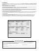

MM-LPS13 Installation Manual ii
rev 05.16.13
IMPORTANT SAFETY INSTRUCTIONS
IMPORTANT SAFETY INSTRUCTIONS
Because automatic gate operators produce high levels of force, consumers need to know the potential
hazards associated with improperly designed, installed, and maintained automated gate operator
systems. Keep in mind that the gate operator is just one component of the total gate operating system.
Each component must work in unison to provide the consumer with convenience, security, and safety.
This manual contains various safety precautions and warnings for the consumer. Because there are
many possible applications of the gate operator, the safety precautions and warnings contained in
this manual cannot be completely exhaustive in nature. They do, however, provide an overview of the
safe design, installation, and use of this product. CAREFULLY READ AND FOLLOW ALL SAFETY
PRECAUTIONS, WARNINGS, AND INSTALLATION INSTRUCTIONS TO ENSURE THE SAFE
SYSTEM DESIGN, INSTALLATION, AND USE OF THIS PRODUCT.
Precautions and warnings in this manual are identified with this
warning symbol. The symbol
identifies conditions that can result in damage to the operator or its components, serious injury, or
death.
Because Mighty Mule automatic gate operators are only part of the total gate operating system,
it is the responsibility of the installer/consumer to ensure that the total system is safe for its
intended use.
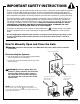
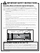
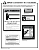
How To Manually Open and Close the Gate:
CAUTION: Disconnect the operator chain ONLY when the power switch on the contol box
is turned off.
Disconnecting the Operator
1. Lift both the quick release pins UP, then pull them OUT
of the chain brackets (see Illustration).
2. Lay the chain down and manually slide the gate to the
desired position.
CAUTION: Because the Mighty Mule gate
operator is battery powered, disconnect the
operator ONLY when the power switch on
the control box is turned OFF. Unplugging
the transformer does not turn power to the
operator OFF.
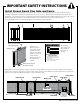
NOTE: To prevent unauthorized removal of the
quick release pins, install
[FM133] pin locks (see
accessories on page 24) above the quick release pins
in both chain brackets.
Insert pin lock (FM133)
shaft through the
Chain Bracket.
Quick Release Pin (211IH)
Secure pin lock
above the Quick
Release Pin.
Chain Bracket (204IH)