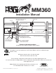
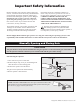
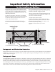
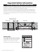
MM360 Installation Manual Receiver Gate Swings Evenly and Freely Hung Firmly and Plumb Warning Sign Post Bracket Assembly Single Gate Opener 120 Volt indoor Transformer (surge protector not supplied) Gate Bracket Closed Position Stop Plate 10’ Battery Harness 12 Volt automotive or marine type battery in weather proof housing (Required, not included). Run 1000' (max.) of low voltage wire to control box from transformer (wire not included).
WARNING This equipment meets Underwriters Laboratory Standard 325 (UL 325). However, gate equipment has hazards associated with its use and therefore by installing this product the installer and user accept full responsibility for following and noting the installation and safety instructions. Failure to follow installation and safety instructions can result in hazards developing due to improper assembly.
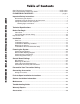
Table of Contents Gate Opener Class Categories......................................................................inside cover Units and Standards Conversion Chart.........................................................inside cover PLEASE READ THIS FIRST!..................................................................... page iv Important Safety Instructions ..........................................................................
Please Read This First! Thank you for purchasing a Mighty Mule Gate Operator—GTO's "do-it-yourself" automatic gate operator! When correctly installed and properly used, your Mighty Mule Gate Operator will give you many years of reliable service. Please read the following information and watch the enclosed video to ensure you have the correct system for your particular needs. Furthermore, this manual and the DVD will enable you to properly install your Mighty Mule Gate Operator.
Important Safety Information Because automatic gate operators produce high levels of force, consumers need to know the potential hazards associated with improperly designed, installed, and maintained automated gate operator systems. Keep in mind that the gate operator is just one component of the total gate operating system. Each component must work in unison to provide the end user with convenience, security, and safety. this manual cannot be completely exhaustive in nature.
Important Safety Information For the Installer and End User WARNING To reduce the risk of injury or death: 1. READ AND FOLLOW ALL INSTRUCTIONS. 2. Never let children operate or play with gate controls. Keep the remote control away from children. 3. Always keep people and objects away from the gate. NO ONE SHOULD CROSS THE PATH OF THE MOVING GATE. 4. Test the gate operator monthly. The gate MUST reverse on contact with a rigid object or stop when an object activates the non-contact sensors.
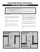
Important Safety Information For the Installer and End User Typical Entrapment Zones are shown in the diagrams on page 2: Zone 1 – leading edge of the gate and the fence post. Zone 2 – between the gate and the gate post. Zone 3 – the path of the gate. Zone 4 – the space between the gate in the open position and any object such as a wall, fence, tree, etc. Zone 5 – pinch points between the operator and gate. II. During Installation 1.
Important Safety Information For the Installer and End User III. After Installation 1. Attach the warning signs (included) to each side of the gate to alert the public of automatic gate operation. It is your responsibility to post warning signs on both sides of your gate. If any of these signs or warning decals becomes damaged, illegible, or missing, replace them immediately. Contact GTO for free replacements. 2. The gate is automatic and could move at any time, posing serious risk of entrapment.
Important Safety Information For the Installer and End User Mighty Mule gate operators utilize Dual Sense Technology™ entrapment protection. Dual Sense Technology™ is built into every Mighty Mule and provides redundant methods of entrapment protection for open and close gate directions. In addition to Dual Sense Technology, every Mighty Mule gate controller has provisions for the connection of additional obstruction detection devices such as sensing edges and photo beams.
Important Safety Information Installing Warning Signs and Pedestrian Gates Warning signs alert people of automatic gate operation and are required when installing Mighty Mule Automatic Gate Operators. A minimum of two WARNING SIGNS must be installed in the area of the gate. Each sign is to be visible by persons located on the side of the gate on which the placard is installed. The operator is intended for installation only on gates used for vehicles. Pedestrians must be supplied with a separate access.
Important Safety Information Required Safety Precautions for Gates These warning labels should be found at the locations specified below. If any of them are missing, immediately contact GTO for replacements. TO MANUALLY OPEN AND CLOSE THE GATE ® 360 1-800-543-GATE (4283) • www.mightymule.com 1. Turn opener power switch OFF. 2. Disconnect front or rear mount from mounting bracket. 3. Pull opener away from mounting bracket and move gate.
Technical Specifications MIGHTY MULE 360 GATE OPENER _____________________________________ ______________________________________ DRIVE • Low friction screw drive (linear actuator) rated for -5 °F to +160 °F (-20 °C to +71 °C). • Powered by a 12 V motor with integral case hardened steel gear reducer. Motor speed reduced to 260 rpm. • Maximum opening arc of 110°. Approximate opening time (90°): 18 seconds, depending on weight of gate.
Before You Begin 1. Determine Charging Options for Battery: Transformer OR Solar NEVER USE TRANSFORMER AND SOLAR PANEL(S) AT THE SAME TIME! It will damage the control board! IMPORTANT: • The 12 volt automotive/marine battery must be charged by either connecting the transformer (included) or solar panel kit to the control board. • The transformer is designed for indoor use.
2. Check Direction of Gate Swing The Mighty Mule Gate Opener is designed for PULL-TO-OPEN installations. PUSH-TO-OPEN installations require a Push-To-Open bracket [FM148, not included]. Push-to-Open Installation Instructions begin on page 32. 3. Prepare the Gate • The gate must be plumb, level, and swing freely on its hinges. • Wheels must NOT be attached to the gate. • The gate must move throughout its arcs without binding or dragging on the ground. • Note that a gate over 250 lbs.
ve rv ie w fo r th e.. . Parts List – Opener and Mounting Hardware In sta lla ti on O ! WARNING ® Installation Video R ENE E OP E-Z GAT Moving Gate Can Cause Injury Or Death Customer Support Card (1) 1. KEEP CLEAR! Gate may move at any time. 2. Do not allow children to operate gate or play in gate area. 3. This gate is for vehicles only. Pedestrians must use a separate entrance.
Tools and Materials Tools Needed: • Power Drill • Open End Wrenches — 1/2" and 9/16" • Adjustable Wrench • 3/8" Drill Bit • Hacksaw or Heavy Duty Bolt Cutters • Small Flat Bladed Screwdriver • Large Phillips Screwdriver • Tape Measure • Level • Wire Strippers • C-Clamps — small, medium, and large • Center Punch • Hammer (for center punch) Note: Not all tools shown. • Extra person will be helpful Materials You May Need for the Installation: These items are NOT included with the gate opener kit.
Installation Overview for Pull-To-Open Gates PUSH-TO-OPEN installation instructions begin on page 32. The diagram shown below is an example of a pull-to-open installation on a chain link fence and single gate. Mounting the opener on a masonry column may require special procedures. Furthermore, if you have a push-to-open gate, you will need to purchase a push-to-open bracket [FM148] to properly configure your system. See Push to Open Installation on page 32 before proceeding.
Installation OF of Mounting INSTALLATION MOUNTINGHardware HARDWARE We recommend you position the opener near the centerline of the gate to keep the gate from twisting and flexing and to avoid back splash from rain water. The Post Bracket Assembly The position of the post bracket assembly determines the leverage and efficiency of the opener. The post bracket assembly position also sets the clearance between the opener and the gate in the open and closed positions.
Install Post Bracket Assembly and Gate Bracket Post Bracket Assembly Step 1 Insert the 3/8" x 2" bolt through the center hole of the post brackets and post pivot bracket as shown. Fasten a 3/8" washer, 3/8" lock washer and 3/8" nut on the end of the bolt. DO NOT overtighten the nut because the post pivot bracket will have to be adjusted later. 3/8" x 2" Bolt NOTE: The following steps are intended for pull-to-open gate installations. If you are mounting your opener on a push-to-open gate (e.g.
IMPORTANT: While determining the mounting point for the post pivot bracket assembly, be sure that the position allows for minimum 2 inches of clearance between the gate and the opener in both the open and closed positions, as shown in the diagrams below. This clearance will give the opener the most efficient leverage point for opening and closing the gate and more importantly provides the least possible pinch area.
Installing the Post Bracket Assembly and Gate Bracket Step 1 Mark reference points for bolt holes on the fence post through middle of bracket slots. Mark reference points for bolt holes on the gate cross member through middle of gate bracket slots. Marking reference points in this manner allows room for adjustment when mounting the post bracket assembly and gate bracket. After marking your reference points, remove the opener and brackets from the fence and gate.
MOUNTING THE OPENER Step 5 Attach the opener to the securely bolted post bracket assembly and gate bracket using clevis pins, bushings, and hairpin clips, or optional Pin Locks (FM133). Verify that the opener is level and adjust the post bracket assembly if necessary.
At this stage of the installation, the opener should be reinstalled on an open gate and the closed position stop plate should be in place. Check List • The gate is plumb, level, and swings smoothly on its hinges. • A plate or support was added for the gate bracket (if necessary). • The opener is level and mounted on the centerline of the gate. • Make sure all hardware is tightened at this time.
CONNECTING THE BATTERY Control Board Access Cover Step 1 ON/OFF With the opener mounted in the upside down position remove the Control Board Access Panel on the bottom of the opener arm. Battery Harness Connector Battery Harness Connector Control Board FF ON/O 10 Foot Power Cable ON/OFF Switch Receiver Wires 20 RED to POSITIVE Step 2 BLACK to NEGATIVE Place the 12 Volt automotive or marine type battery and its weatherproof case within 6 feet of the fence post where the opener arm is mounted.
IMPORTANT: Detailed Wire Routing Diagrams The battery harness wire has an in-line fuse that must be placed inside the battery box when connecting the battery to the opener. The illustration to the right shows the best placement for the battery harness wire and connector inside the arm.
CONNECTING THE TRANSFORMER IMPORTANT: Never connect the transformer and a solar panel to the opener control board at the same time. It will damage the control board. IMPORTANT: If you are using SOLAR PANEL(S) to charge the opener battery, skip this section and go to "Connecting Solar Panel(s)" section on page 24. IMPORTANT INFORMATION ABOUT LOW VOLTAGE WIRE The only wire acceptable for use with GTO products is 16 gauge dual conductor, stranded, direct burial wire.
15 2 3 4 Strip 3/16" off the ends of the low voltage transformer wire and twist tightly. Insert these ends to the 18 VAC terminal block located on the control board (see illustration at right). Wrong RED BLK GRN COMMON CYCLE 18VAC/ SOLAR INPUT EDGE H L AUX OUT SAFETY LINK Tighten set screws against exposed end of wires.
CONNECTING THE SOLAR PANEL(S) SET LEARN 15 REMOTE IMPORTANT: Never connect the transformer and a solar panel to the opener control board at theLIMIT same time. It will damage the control board. 1 ON PULL-PUSH 2 If you are using the transformer included with the Mighty Mule Gate Opener to charge the opener battery,MODE1 skip MODE2 this section and go to "CONTROL BOARD SETTINGS" below. LOCK/BEACON 3 4 NOTE: For multiple panels wire the panels in parallel as shown in this diagram.
STATUS CONTROL BOARD SETTINGS Control Board Settings MIN MAX STALL FORCE DIP Switches OFF 1 2 3 4 2 3 4 PULL-PUSH MODE1 MODE2 LOCK/BEACON PULL-PUSH CHARGING MODE1 POWER MODE2 LOCK/BEACON RF BLK RED GRN COMMON SOLAR PANEL EDGE EXIT AUX OUT CYCLE LINK 18VAC SAFETY DIP Switch #4 - Lock/Beacon This DIP selects the mode of operation of the "AUX OUT" terminal. ON 1 NOTE: if you have a Push-to-Open gate application see Push-to-Open Instructions on page 32.
SETTING THE CLOSED POSITION LIMIT Setting the Closed Position Limit For PULL-TO-OPEN Installation Turn the power switch on to the ON position Step 1 Power switch is on, gate is in the OPEN position, opener arm fully F retracted. N/OF FF ON/O Gate in OPEN Position O Step 2 Gate Closing Press the transmitter to activate opener arm. The gate will begin to CLOSE. NOTE: If gate stops and STATUS reverses you may need to adjust the Stall Force (see page 27).
Setting Dual Sense Detection and Auto Close Timer Do not use the Dual Sense Stall Force adjustment to compensate for a gate that is sticking or binding. Excessive Stall Force may cause damage to the gate operator or gate system or Injury or Death. STATUS The Stall Force adjustment controls the amount of force the opener will apply against an obstruction before it stops and reverses direction. The adjustment on the control board operates like a volume control on a radio.
PERSONALIZE YOUR TRANSMITTER SETTING All GTO transmitters have a standard setting and are ready to operate your Mighty Mule Gate Opener. For your safety and security, we strongly recommend that you replace the factory setting with your own personal setting. NOTE: If you have multiple transmitters, you should adjust all of them at this time. All transmitters should have the same DIP switch setting. Step 1 Use a small phillips head screw driver to remove the transmitter cover. LE D Step 2.
CONNECTING ACCESSORIES Before You Begin Mighty Mule strongly recommends the use of additional obstruction detection devices however we do not endorse any specific brand names. Only use products that are listed to be in compliance with any applicable UL safety standards and national and regional codes. PLEASE NOTE: Contact sensors, non-contact sensors, shadow loops, etc. are not included with the Mighty Mule. Refer to the sensor manufacturer’s instructions for information about installing accessory devices.
WIRING ACCESSORIES CHARGING POWER RED 1 BLK 2 GRN 3 COMMON 4 CYCLE BLACK 5 EDGE 6 18VAC/ SOLAR INPUT SAFETY 7 RED H L AUX OUT EXIT LINK RCVR DIP switch 4 set to OFF position (Default) 3 1 Automatic Gate Lock (FM143) Edge Sensor 1 (+12 v) 2 Push Button Control (–) 4 1 1 4 GHI 7 PRS 2 ABC 5 JKL 8 TUV Photo Beams (R4222) 3 DEF 6 MNO 9 WXY 0 1 (+12 v) 2 (–) 5 1 Keypad (FM137) Vehicle Sensor (FM138) (See additional wiring digram on pg.
Mighty Mule Gate Opening Sensor (FM138) MIN MAX STALL FORCE The Gate Opening Sensor is designed for residential and agricultural applications and is compatible with Mighty Mule automatic gate openers. The Sensor is an electromagnetic sensor, which offers 'hands free' operation of the Mighty Mule CLOSE TIME Gate Opener with a 12 ft. radius of detection of vehicles in motion.
PUSH-TO-OPEN INSTALLATION INSTRUCTIONS Swinging gates MUST NEVER open into public access areas! Step 1 Insert the 3/8" x 2" bolt through the center hole of the post brackets and post pivot bracket as shown. Fasten a 3/8" lock washer, 3/8" washer and 3/8" nut on the end of the bolt. DO NOT over tighten the nut because the post pivot bracket will have to be adjusted later. Step 2 Attach post bracket assembly and gate bracket to the opener with the clevis pins and bushings.
Step 4 When you feel that you have the best position for the post pivot bracket in the closed position, insert the 5/16" bolt through the aligned holes of the post bracket and post pivot bracket to hold it in place. Remove the clevis pin from the front mount and while supporting the gate opener, swing the gate and gate opener to the open position. With the gate and gate opener in the open position check the clearance and be sure that the gate opener is not binding at the post pivot bracket.
MIN MAX STALL FORCE Set Control Board for Push-To-Open LEARN REMOTE 15 1 2 3 4 ON 1 2 3 4 PULL-PUSH MODE1 MODE2 LOCK/BEACON PULL-PUSH CHARGING MODE1 POWER MODE2 LOCK/BEACON RF BLK RED GRN COMMON SOLAR PANEL EDGE EXIT AUX OUT CYCLE LINK 18VAC SAFETY Make sure the control box power switch is OFF. Use a small screwdriver to move the Number 1 DIP switch from the factory setting (OFF / Pull-To-Open) to ON for Push-To-Open. Turn power switch ON.
MAINTENANCE Monthly, test the obstruction and entrapment protection systems. Monthly, service the gate operator (make sure the power switch is OFF). Clean extended operator arm with a soft, dry clean cloth. After cleaning, apply a high quality silicon spray to a soft dry cloth and wipe the push/ pull tube. DO NOT directly spray the tube! On all gates weighing 250 lb. or more, routinely grease the ball bearing hinges at least 4 times a year; more frequently if the gates are near a coastal area.
TROUBLESHOOTING GUIDE AUDIBLE/BUZZER/ALARM FEEDBACK: 1. 1 beep with 2 seconds pause and repeats: Limit switch error: Limit switch’s normally open and normally closed inputs both open or both shorted. The alarm will automatically shut off in 4 seconds after the problem is corrected. 2. 5 beeps with 2 seconds pause and repeats: Low battery condition detected: Low battery can occur if the following condition is detected: While in idle state and the battery voltage is below ~11.5 Volts.
3. POWER LED (Green): ON: AC power or solar power is presented. OFF: NO AC power or solar power is presented. Check your charging source; transformer or solar panel. 4. CHARGING LED (Red): Red light on or flashing – the unit is charging Red light off – the unit is not charging. Check transformer or solar panel. THE GATE CLOSES THEN OPENS PARTIALLY: 1. Check the position of the mounting brackets and readjust if necessary. 2. Check the gate for binding or hinge damage. 3. Increase Stall Force setting.
WARRANTY REPAIRS If your Mighty Mule Gate Opener is not operating properly, please follow the steps below: 1. First use the procedures found in the Visual and Audible Diagnostic Indicators section (page 35). 2. If you are unable to solve the problem, call the GTO Service Department at (800) 543-1236, or (850) 575-4144. Refer to the serial number (located under rear mount on arm) and date of purchase when calling for assistance. 3.
ACCESSORIES Accessories are Available From Your Retail Store Solar Panel Kits [FM121/FM123] If your gate operator is more than 1000 ft. away from an AC power outlet, you can choose to maintain the battery charge with the GTO Solar Panel Kit. • 10 Watt Solar Panel Charging Kit [FM123] • 5 Watt Solar Panel Charging Kit [FM121] Push Button Control [FM132] Unlit doorbell button for remote entry or exit control.
Accessories are Available From Your Retail Store (con't) 3 AC CE SS 1-8 CO 00 NT -54 RO 3-4L SY 28 ST EM S Ans wer Key Ba pad tt Low Per Grant mis sio n POW ER Wireless Entry Intercom / Keypad [FM136] DV 9V Allows owner to screen guest at the gate before allowing access to the property. Keypad also allows owner to give up to 25 programmable entry codes to family, friends or approved delivery personnel. Codes can be permanent or temporary. Can be wireless up to 500 feet.
Gate Operator Installation Checklist 1. The gate has been checked to make sure it is level and moves freely in both directions. 2. Potential pinch areas have been guarded so as to be inaccessible OR have sensing edges and/or photo beam obstruction detection devices installed. 3. The installer has installed one or more contact or non-contact obstruction sensing devices, if required for this installation. 4.