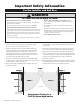
MM462 Installation Manual Receiver Control Box Gate Swings Evenly and Freely Hung Firmly and Plumb Warning Sign First Gate Opener 120 Volt indoor Transformer Second Gate Opener Gate Bracket Post Bracket Gate Bracket Post Bracket Horizontal Support (surge protector not supplied) Horizontal Support Power Cable Run 1000' (max.) of low voltage wire to control box from transformer (wire not included). PVC conduit (not included) to protect wire from lawn mowers and weed eaters.
WARNING This equipment meets Underwriters Laboratory Standard 325 (UL 325). However, gate equipment has hazards associated with its use and therefore by installing this product the installer and user accept full responsibility for following and noting the installation and safety instructions. Failure to follow installation and safety instructions can result in hazards developing due to improper assembly.
Table Of Contents Please Read This First....................................................................................................ii Important Safety Instructions................................................................................... iii–viii How to Manually Open and Close the Gate:............................................................... iii For the Consumer........................................................................................................
Please Read This First! Thank you for purchasing a Mighty Mule Gate Operator—GTO's "do-it-yourself" automatic gate operator! When correctly installed and properly used, your Mighty Mule Gate Operator will give you many years of reliable service. Please read the following information and watch the enclosed video to ensure you have the correct system for your particular needs. Furthermore, this manual and the DVD will enable you to properly install your Mighty Mule Gate Operator.
Important Safety Information Because automatic gate operators produce high levels of force, consumers need to know the potential hazards associated with improperly designed, installed, and maintained automated gate operator systems. Keep in mind that the gate operator is just one component of the total gate operating system. Each component must work in unison to provide the end user with convenience, security, and safety. this manual cannot be completely exhaustive in nature.
Important Safety Information For the Installer and End User WARNING To reduce the risk of injury or death: 1. READ AND FOLLOW ALL INSTRUCTIONS. 2. Never let children operate or play with gate controls. Keep the remote control away from children. 3. Always keep people and objects away from the gate. NO ONE SHOULD CROSS THE PATH OF THE MOVING GATE. 4. Test the gate operator monthly. The gate MUST reverse on contact with a rigid object or stop when an object activates the non-contact sensors.
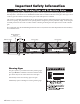
Important Safety Information For the Installer and End User Typical Entrapment Zones are shown in the diagrams on page iv: Zone 1 – leading edge of the gate and the fence post. Zone 2 – between the gate and the gate post. Zone 3 – the path of the gate. Zone 4 – the space between the gate in the open position and any object such as a wall, fence, tree, etc. Zone 5 – pinch points between the operator and gate. II. During Installation 1.
Important Safety Information For the Installer and End User III. After Installation 1. Attach the warning signs (included) to each side of the gate to alert the public of automatic gate operation. It is your responsibility to post warning signs on both sides of your gate. If any of these signs or warning decals becomes damaged, illegible, or missing, replace them immediately. Contact GTO for free replacements. 2. The gate is automatic and could move at any time, posing serious risk of entrapment.
Important Safety Information For the Installer and End User Mighty Mule gate operators utilize Dual Sense Technology™ entrapment protection. Dual Sense Technology™ is built into every Mighty Mule and provides redundant methods of entrapment protection for open and close gate directions. In addition to Dual Sense Technology, every Mighty Mule gate controller has provisions for the connection of additional obstruction detection devices such as sensing edges and photo beams.
Important Safety Information Installing Warning Signs and Pedestrian Gates Warning signs alert people of automatic gate operation and are required when installing Mighty Mule Automatic Gate Operators. A minimum of two WARNING SIGNS must be installed in the area of the gate. Each sign is to be visible by persons located on the side of the gate on which the placard is installed. The operator is intended for installation only on gates used for vehicles.
Important Safety Information Required Safety Precautions for Gates These warning labels should be found at the locations specified below. If any of them are missing, immediately contact GTO for replacements. ® 462 1. KEEP CLEAR! Gate may move at any time. 2. Do not allow children to operate gate or play in gate area. 3. This gate is for vehicles only. Pedestrians must use separate entrance. Maximum Gate: 300 lbs. (136.1 kg); 12 ft. (3.
Technical Specifications MIGHTY MULE MM462 GATE OPENER _____________________________________ ______________________________________ DRIVE • Low friction screw drive (linear actuator) rated for -5 °F to +160 °F (-20 °C to +71 °C). • Powered by a 12 V motor with integral case hardened steel gear reducer. Motor speed reduced to 260 rpm. • Maximum opening arc of 110°. Approximate opening time (90°): 18 seconds, depending on weight of gate.
Before You Begin 1. Determine Charging Options for Battery: Transformer OR Solar NEVER USE TRANSFORMER AND SOLAR PANEL(S) AT THE SAME TIME! It will damage the control board! IMPORTANT • The battery charge is maintained by the 14 Volt transformer included OR optional solar panel(s). The transformer OR solar panel is connected to the control board using low voltage, 16 gauge, dual conductor, stranded, direct burial wire [RB509] (page 26).
2. Check Direction of Gate Swing The Mighty Mule is designed for PULL-TO-OPEN installations. PUSH-TO-OPEN installations require two Push-To-Open brackets [FM148]. Push-to-Open Installation Instructions begin on page 19. Your Property Your Property Push-To-Open Pull-To-Open (arm retracts to open) (arm extends to open) 3. Prepare the Gates • Gates must be plumb, level, and swing freely on their hinges. • Wheels must NOT be attached to the gates.
Parts List – Opener and Mounting Hardware ! WARNING Installation DVD (1) Battery (1) Moving Gate Can Cause Injury Or Death Transformer (1) GTO Transmitter(2) 1. KEEP CLEAR! Gate may move at any time. 2. Do not allow children to operate gate or play in gate area. 3. This gate is for vehicles only. Pedestrians must use a separate entrance.
Tools and Materials Tools Needed: • Power Drill • Open End Wrenches — 1/2" and 9/16" • Adjustable Wrench • 3/8" Drill Bit • Hacksaw or Heavy Duty Bolt Cutters • Small Flat Bladed Screwdriver • Large Phillips Screwdriver • Tape Measure • Level • Wire Strippers • C-Clamps — small, medium, and large • Center Punch • Hammer (for center punch) • Extra person will be helpful Materials You May Need for the Installation: These items are NOT included with the gate opener kit.
Installation Overview for Pull-To-Open Gates PUSH-TO-OPEN installation instructions begin on page 19. Example of an installation on a chain link fence: Control Box / Battery Box 120 Volt indoor Transformer Gate Swings Evenly and Freely Hung Firmly and Plumb First Opener Second Opener (surge protector not supplied) Gate Bracket Closed Position Stop Plates Run 1000' (max.) of low voltage wire to control box from transformer (wire not included).
Installation of the FIRST Gate Opener IMPORTANT: Determine which side of the driveway you will mount the control box. From this point on, the gate and gate opener on the same side as the control box will be referred to as the FIRST gate and gate opener. The gate and gate opener on the opposite side of the driveway from the control box will be referred to as the SECOND gate and gate opener.
Step 1 Insert the 3/8" x 11/2" bolt through the center hole of the post brackets and post pivot bracket. Secure with a 3/8" washer and 3/8" lock nut. DO NOT overtighten the lock nut (the post pivot bracket will have to be adjusted later). Step 2 Attach post bracket assembly to the rear mount of the opener with a clevis pin and a 3/8" washer. Secure the clevis pin with a hairpin clip.
Step 5 Be sure the position of the gate opener and brackets allows for 1" of clearance between the gate and the opener in both the open and closed position, while at the same time maintaining a stroke distance of 7" to 13" from center of hole in the end of the retracted opener arm to the center of the hole in the gate bracket with the gate in the closed position. This mounting position will give the opener the most efficient leverage point for operation and provides the least possible pinch area.
Step 9 Drill 3/8" holes through post as marked. Fasten post bracket assembly to the fence post using two 3/8" x 8" bolts, washers and lock nuts. You Gate Post Bracket Mounting Examples must use bolts that completely penetrate the post. EXAMPLES TOP VIEW Round Metal Post Step 10 Drill 3/8" holes through the gate cross member as marked. Mount gate bracket using two 3/8" x 2 3/4" bolts, washers, and lock nuts.
Install the Closed Position Stop Plates The closed position stop plate is attached to the FIRST gate to help stabilize the gate leaf in the closed position. An optional low profile ground stop, when used with the closed position stop plate, provides a secure point for the SECOND gate to close against. To further enhance the stability and security of your gate, install a Mighty Mule Automatic Gate Lock [FM143] page 26).
Step 4 Closed Position Stop Plate mounted on the SECOND GATE Mount Vertically Using appropriate hardware for your type of gate, attach the vertical closed position stop plate to the SECOND gate frame at the point where it will come in contact with the low profile ground stop. Do not tighten it completely at this time. You must slide the closed position stop plate toward the low profile ground stop until they touch.
Connecting the Battery Step 4 Verify that the ON/OFF switch is in the OFF position. Battery Connect the BATTERY WIRE HARNESS wires to the battery --- RED wires to POSITIVE (+) battery terminal and BLACK wires to NEGATIVE (–) battery terminal. The BATTERY WIRES from the CONTROL BOARD should extend through the KNOCK-OUT in the back of the CONTROL BOX. Plug the BATTERY HARNESS wires into the wires coming from the CONTROL BOX.
Connect Opener Power Cables Step 1 STATUS 1st OPR. Bring FIRST power cable into the control box through a strain relief slot, leaving enough wire to reach the FIRST OPR. terminal block. OPEN < JOG > CLOSE 2nd OPR. PWR. Insert the individual power cable wires into appropriate terminals on the FIRST OPR. terminal block (white to WHT; green to GRN; red to RED; black to BLK). Tighten the set screws. A dab of petroleum jelly on each terminal will help prevent corrosion.
Step 3 Control and Battery Box First Gate Opener 120 Volt indoor Transformer Lay the measured length of low voltage wire in a trench following a path from the selected electrical outlet to the control box. Wires coming up from the ground should be run through PVC conduit to protect them from lawn mower blades, weed eaters, and grazing animals. Be sure to bury the wire laid in the trench. (surge protector not supplied) Run 1000' (max.
Step 7 Transformer SURGE PROTECTOR Plug the transformer into the electrical outlet. Use of a surge protector with the transformer is strongly recommended. If electrical outlet is located outdoors, outlet and transformer should be protected by a weatherproof cover. Set the CLOSED Position Limit for PULL-TO-OPEN Installation Your transmitter must be able to operate the gate. If not, see "Personalize Your Transmitter Setting" on page 18.
Setting Dual Sense Detection and Auto Close Timer Do not use the Dual Sense Stall Force adjustment to compensate for a gate that is sticking or binding. Excessive Stall Force may cause damage to the gate operator or gate system or Injury or Death. The Stall Force adjustment controls the amount of force the opener will apply against an obstruction before it stops and reverses direction. The adjustment on the control board operates like a volume control on a radio.
Personalize Your Transmitter Setting All GTO transmitters have a standard setting and are ready to operate your Mighty Mule Gate Opener. For your safety and security, we strongly recommend that you replace the factory setting with your own personal setting. NOTE: If you have multiple transmitters, you should adjust all of them at this time. LE Step 1 D Use a small phillips head screw driver to remove the transmitter cover.
Push-To-Open Installation Instructions PUSH-TO-OPEN gates open out from the property (opener arms extend to open). Push-To-Open Brackets are required for this type of installation, one for each gate [FM148] page 26).). In a Push-To-Open installation, the opener is installed while the gate is in the closed position and the opener fully retracted. Swinging gates MUST NEVER open into public access areas! Step 1: Read "Installation of the First Opener" on page 7.
Step 3: Attach Opener Arm (page 10) Step 4: Install Closed Position Stop Plates (page 11) Step 5: Install the Control / Battery Box (page 12) Step 6: Connect Battery Harness (page 13) Step 7: Connect Opener Power Cables (page 14) Step 8: Connect the Transformer (page 14) OR Solar Charger (page 21) Step 9: Remove Push-To-Open Jumper A. Make sure the control box power switch is OFF. B. Use small pliers to remove the JUMPER for PUSH-TO-OPEN applications. STATUS 1st OPR. OPEN < JOG > CLOSE C.
Solar Panel Instructions NEVER USE TRANSFORMER AND SOLAR PANEL(S) AT THE SAME TIME! It will damage the control board! IMPORTANT INFORMATION ABOUT LOW VOLTAGE WIRE: • The only wire acceptable for use with GTO products is 16 gauge stranded, low voltage, PVC sheathed wire. This particular gauge enables the solar panel to provide an adequate charge through the control board to the battery at distances up to 250'. • DO NOT use telephone wire or solid core wire.
Connecting Additional Devices Mighty Mule strongly recommends the use of additional obstruction detection devices however we do not endorse any specific brand names. Only use products that are listed to be in compliance with any applicable UL safety standards and national and regional codes. PLEASE NOTE: Contact sensors, non-contact sensors, shadow loops, etc. are not included with the Mighty Mule. Refer to the sensor manufacturer’s instructions for information about installing accessory devices.
STATUS 1st OPR. OPEN < JOG > CLOSE 1 2nd OPR. SAFETY: Typically for use with photo beam device, loop PWR. detector or other non-contact sensors MIN SET LIMIT Activation of this input while the gate is closing will cause the gate to stop and return to the opened position. • Activation of this input while the gate is opening has no effect. (gate will continue to open) 1 SFTY. 2 EXIT Activation of this input while gate is idle will prevent gate from closing.
Troubleshooting Guide If your gate opener does not function properly, use this guide or use the online troubleshooter at http://support.gtoinc.com before calling the GTO Service Department. VISUAL AND AUDIBLE DIAGNOSTIC INDICATORS 1. VISUAL INDICATORS: a. Power LED (Green): • ON: AC power or Solar power is present. • OFF: There is no input power. 2. AUDIBLE INDICATORS (ALARM/BUZZER): a. Beeps upon power up: • This is normal self test when the unit is turned on. b.
VOLTAGE READINGS 14 Vac Transformer______________ 13.0 to 16.0 Vac 10 W Solar panel ________________ 18.0 to 22.0 Vdc 600 mA Measure voltage at panel and control box. 12 V Battery_____________________ 12.5 to 13.5 Vdc Charging circuit _________________ 13.8 to 14.8 Vdc Measure voltage at battery terminals with battery connected.
Maintenance Monthly, test the obstruction and entrapment protection systems. Monthly, service the gate operator (make sure the power switch is OFF). Clean extended operator arm with a soft, dry clean cloth. After cleaning, apply a high quality silicon spray to a soft dry cloth and wipe the push/pull tube. DO NOT directly spray the tube! On all gates weighing 250 lb. or more, routinely grease the ball bearing hinges at least 4 times a year; more frequently if the gates are near a coastal area.
Accessories Please visit www.mightymule.com for photos and detailed descriptions of Mighty Mule Accessories, or call Mighty Mule sales 1-800-543-4283. Solar Panel (FM123) 10 watt If your gate is more than 1000' from an AC power source, you can choose to maintain the battery charge with the Solar Panel Charging Kit. Installation in some regions of the world will require multiple solar panels for adequate charging power.
DV 9V AC 3 CE SS 1-8 CO 00 NT -54 RO 3-4L SY 28 ST EM S Ans wer Per Grant mis sio n Key Ba pad tt Low POW ER Accessories are Available From Your Retail Store (con't) Wireless Entry Intercom / Keypad (FM136) Allows owner to screen guest at the gate before allowing access to the property. Keypad also allows owner to give up to 25 programmable entry codes to family, friends or approved delivery personnel. Codes can be permanent or temporary. Up to 500 feet reception.
Gate Operator Installation Checklist 1. The gate has been checked to make sure it is level and moves freely in both directions. 2. Potential pinch areas have been guarded so as to be inaccessible OR have sensing edges and/or photo beam obstruction detection devices installed. 3. The installer has installed one or more contact or non-contact obstruction sensing devices, if required for this installation. 4.
For sales call toll free: 1-800-543-GATE (4283) The Sales Department is open Monday – Friday 8:00 A.M. – 5:00 P.M. (Eastern Time) For technical service Call toll free: 1-800-543-1236 The Technical Service Department is open Monday – Friday 8:00 A.M. – 7:00 P.M. (Eastern Time) 3121 Hartsfield Road • Tallahassee, Florida, USA 32303 www.mightymule.