
Installation Guide

MM462 Installation Instructions 21
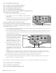
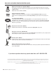
VAR5
VAR6
K1
PF1
K2
BATT +
BATT –
K3
K4
VAR4
VAR3
VAR2
VAR1
MIN
MAX
OFF
JP1
REMOVE JUMPER FOR
PUSH TO OPEN OPTION
120
SEC.
GTO Inc. Tallahassee, FL
R4722
STALL FORCE
OPEN < JOG > CLOSE
PWR.
SET
LIMIT
1st OPR.
2nd OPR.
STATUS
AUTO CLOSE
SFTY.
EXIT
CYCLE
EDGE
SENSOR
COMMON
LOCK+
LOCK–
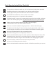
WHT
GRN
RED
BLK
WHT
GRN
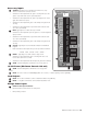
SECOND OPR.FIRST OPR.
RED
BLK
14 VAC
OR
SOLAR
ON OFF
Low Voltage Wire from
Transformer or Solar
VAR6
BATT +
K3
K4
WHT
GRN
SECOND OPR.
RED
BLK
14 VAC
OR
SOLAR
ON OFF
Low Voltage Wire
from Transformer
or Solar Panel
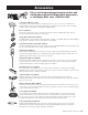
NEVER USE TRANSFORMER AND SOLAR PANEL(S) AT THE SAME TIME!
It will damage the control board!
IMPORTANT INFORMATION ABOUT LOW VOLTAGE WIRE:
• The only wire acceptable for use with GTO products is 16 gauge stranded, low voltage, PVC sheathed wire. This
particular gauge enables the solar panel to provide an adequate charge through the control board to the battery
at distances up to 250'.
• DO NOT use telephone wire or solid core wire. Unlike stranded wire, these types of wire are inadequate for use
with your gate opener system.
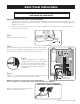
Step 1
Make sure the power switch is OFF.
Step 2
Strip 3/16" off the ends of the low voltage wire and twist tightly. Attach
these ends to the 14VAC OR SOLAR terminals located on the terminal
block. Be certain not to let the exposed wires touch each other!
Step 3
Insert one solar panel wire into a 14VAC OR
SOLAR terminal. Insert the other solar panel
wire into the remaining 14VAC OR SOLAR
terminal. The wires can be connected to the
14VAC OR SOLAR terminals regardless of
color/polarity.
Step 4
Tighten set screws against exposed end of wires. A dab of household
petroleum jelly on each terminal will help prevent corrosion.
AFTER connecting the solar panel(s) set the CLOSE LIMIT as
shown on page 16 or if push-to-open see page 20 and continue installation.
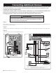
NOTE: For multiple panels, wire the panels in
parallel as shown in this diagram.
ON/OFF
Switch
ON/OFF
Solar Panel Instructions
RED
RED
BLACK
BLACK
Solar Panels connect in PARALLEL