
Product Manual


MM562 Installation Instructions 35
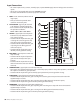
If your gate opener does not function properly after it is installed, use this guide before calling the GTO Service Department.
Audible Feedback
Indication Possible Diagnosis Check
1 short beep upon activation Blown Fuse
Low or Bad Battery
Loose Battery Connection
• Fuse
• Battery Under Load
• Battery Harness Connections
A series of beeps that stop
and do not repeat after
power-up
Circuit Board Powered Up &
Ready
• Normal Operation
Continuous Uninterrupted
Alarm
Circuit Board Senses an
Obstruction
• Path of Gate
• Gate for Level and Plumb
• Stall Force Adjustment
• For diagnostic purposes, temporarily disconnect the
external obstruction detection devices
• Rev Counter
1 beep with 10 seconds off Low Battery Condition • Fuses
• Battery Harness Connections
• Battery Under Load
1 beep then 2 beeps, then
pause and repeats
Master Motor Terminals
Shorted
• Connections to Master Inputs
• Master Arm Power Cable
• Motor
• Circuit Board
1 beep then 3 beeps, then
pause and repeats
Second Motor Terminals
Shorted
• Connections to Second Inputs
• Second Arm Power Cable
• Motor
• Circuit Board
1 beep with 2 seconds, then
pause and repeats
Master Arm Limit Switch
Error
• Connections to Master Inputs
• Master Arm Power Cable
2 beeps with 2 seconds, then
pause and repeats
Second Arm Limit Switch
Error
• Connections to Second Inputs
• Second Arm Power Cable
3 beeps with 2 seconds, then
pause and repeats
Master Arm Rev Counter
Error
• Connections to Master Inputs
• Master Arm Power Cable
• Rev Counter
4 beeps with 2 seconds, then
pause and repeats
Second Arm Rev Counter
Error
• Connections to Second Inputs
• Second Arm Power Cable
• Rev Counter
Troubleshooting Guide
VOLTAGE READINGS
18 Vac Transformer .....................................................................................18.0 to 22.0 Vac, 2200 mA
5 W Solar panel (single) ............................................................................18.0 to 22.0 Vdc, 300 mA
* measure voltage at panel and control box in full sun; this will increase by approximately 300mA for
each additional solar panel.
Two 12 V, 7 amp hour Batteries .............................................................12.5 to 13.5 Vdc 7.0 Ah
*measure voltage at battery terminals with battery disconnected from circuit board
Charging circuit ..........................................................................................13.3 to 14.8 Vdc
*measure voltage at battery terminals with battery connected to circuit board and GREEN "POWER IN"
LED is ON.