
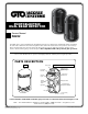
Installation Guide


Symptom Possible Cause Remedy
Transmitter LED does not light. Improper voltage supplied. Check the power supply and wiring.
Receiver LEDs do not light. Improper voltage supplied. Check the power supply and wiring.
Alarm LED does not light,
even when beams are blocked.
1. Beams reect to the receiver
by other objects.
2. Both beams are not blocked
simultaneously.
3. Beam interruption time is too short.
1. Remove the reecting object or change
optical axis direction.
2. Block both beams.
3. Increase beam interruption time
adjustment.
When beams are blocked, receiver LED
lights are ON, but not alarm.
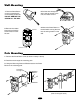
1. Wiring is short circuited.
2. Wiring connection is not good.
Check wiring and connection spot.
The alarm indication lamp of receiver is
always on.
1. Optical axis is not properly adjusted.
2. There are obstructions between the
transmitter and the receiver.
3. The outer covers are dirty.
1. Adjust the optical axis.
2. Remove the obstructions.
3. Clean with window cleaner and a
soft cloth.
Intermittent Alarm (detection)
*If you’re experiencing false detections
then increase the time adjustment by 1
increment at a time until the photo beam
functions as desired.
1. Bad wiring.
2. Fluctuating power supply / voltage.
3. Intermittent blockage between the
transmitter and the receiver.
4. The receiver or transmitter is unstable.
5. Blocked by other moving objects.
6. Beam interruption time out of adjustment.
1. Check wiring.
2. Check the power supply.
3. Remove the obstruction or relocate.
4. Fix the mounting.
5. Adjust the optical axis.
6. Adjust interruption time or change
installation position.
MODEL R4222
Detection Method Infrared photoelectric
Range Outdoor 98.4 ft (30m)
Indoor 295.2 ft (90m)
Beam Characteristics Pulsed infrared dual beams
Response Time 50~700msec (selectable)
Power Input DC12.5~24V / AC11~18V
Current Consumption 40mA max
Output Pulse Duration 2Sec (±1)nominal
Alarm Output Form B relay (AC/DC 30V 0.5A max)
Tamper Switch N.O. contact is open when cover is removed (transmitter and reciever)
Operating Temperature -13˚F (-25˚C)~131˚F (55˚C)
Environment Humidity 95% max
Alignment Angle 20˚±10˚ vertical, ±90˚ horizontal
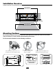
Mounting Wall or pole
Weight .66lbs (300g) Both transmitter and receiver
Appearance PC Resin (Black)
Condition Indication
Transmitter
Transmitting POWER LED is ON
Receiver
Beam Not Blocked GOOD and LEVEL LEDs are ON
Beam Blocked ALARM LED is ON
VERIFY CORRECT OPERATION
TROUBLESHOOTING
SPECIFICATIONS
After installation, conrm
correct operation by suitable
walking tests. Refer to the
appropriate LED indicators
during the walking test and
ensure the gate opener
operates in the correct manner.
For optimal
efciency, wipe
the outer cover
frequently with a
soft, damp cloth.
Not compatible
with Solar Panels.
For online Technical Support visit the Online Troubleshooter Wizard 24 hrs/day 7 days/week at
http://support.gtoinc.com/support/troubleshooter.aspx and open a Tech Ticket
Technical Support Hours: MON - FRI 8:00AM - 7:00PM (ET) (800) 543-1236