
Installation Guide
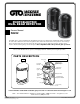


2
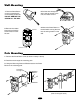
Mounting Cautions
Where obstructions (plants, fences, etc.)
are between the receiver and the sender.
Where the mounting
surface is unstable.
Where sunlight and headlights shine
directly into the front of the receiver.
Mounting Height
Sensing Area
Spread of Beam
Beam Alignment
Range
Horizontally 180°
The optical axis can be fine tune
adjusted in horizontal and
vertical direction.
Up/Down Direction
20° (±10° )
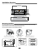
Installation Overview
Vehicular Gate
Exterior placement
of Photo Beams
(placed outside of path of gate)
Interior placement
of Photo Beams
(placed outside of path of gate)
Be sure that the optical axis is never obstructed. (The optical axis is both the vertical and horizontal
range of detection, or beam, between the transmitter and receiver)
Do not mount the detector in the following conditions:
When using more than one set make
sure to alternate the transmitters
and detectors as above.
Transmitter
Receiver
Transmitter
Receiver
Transmitter
Transmitter
Receiver
Receiver
Diagram illustrates correct placement of photo beams in relation to the gate.