
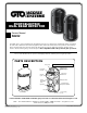
Installation Guide


5
TAMPER
6
7
+ –
POWER
INTERIOR TOP OF
TRANSMITTER
12 Volt Battery or
12Vdc source
RECEIVER
ALM
GTO RCVR.
COM
GRN
BLK
RED
CYCLE
SAFETY
EXIT
SHADOW
OPEN
EDGE
COM
CONTROL INPUTS
CLOSE
EDGE
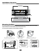
Transmitter/Receiver Connections
Wires from Photo Beams
INTERIOR TOP OF
RECEIVER
TAMPER
6
7
1 2 3 4 5 6 7
POWER
ALARM
+ –
1 2 6 7
To + Pos Terminal of Battery
To - Neg Terminal of Battery
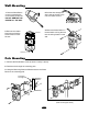
Connections for
GTO Access Systems 2000XL,
3000XL, 4000XL; Mighty Mule FM500
and FM600 Control Boards
1. Connect 1 and 2 power terminals
of the transmitter to the 1 and 2
power terminals of the receiver.
2. Connect 1 and 2 power terminals
of the Receiver OR Transmitter to
the battery.
3. Connect 3 and 5 terminals of the
receiver to the COM and SAFETY
terminals on the control board.
Wiring the Photo Beams to GTO Access Systems and
Mighty Mule Gen 3 (blue) or green Gate Opener Control Boards.
(models listed below)