
Installation Guide
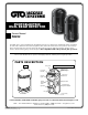


6
CHARGING
POWER
AUX OUT
SOLAR
PANEL
18VAC
RECR
GRN
BLK
RED
EXIT
SAFETY
EDGE
CYCLE
COMMON
LINK
TAMPER
6
7
+ –
POWER
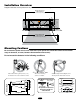
INTERIOR TOP OF
TRANSMITTER
12 Volt Battery or
12Vdc source
Transmitter/Receiver Connections
Wires from Photo Beams
INTERIOR TOP OF
RECEIVER
TAMPER
6
7
1 2 3 4 5 6 7
POWER
ALARM
+ –
1 2 6 7
To + Pos Terminal of Battery
To - Neg Terminal of Battery
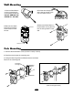
Connections for FM350 and
FM352 Control Boards
Wiring the Photo Beams to Mighty Mule FM350 Gate Opener Control
Board.
1. Connect 1 and 2 power terminals
of the transmitter to the 1 and 2
power terminals of the receiver.
2. Connect 1 and 2 power terminals
of the Receiver OR Transmitter to
the battery.
3. Connect 3 and 5 terminals of the
receiver to the COM and SAFETY
terminals on the control board.