
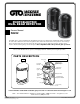
Installation Guide


7
Wiring the Photo Beams to GTO Access Systems GP-SL050, GP-SW050,
GP-SL100 and GP-SW100 Gate Opener Control Boards.
COM
COM
COM
CYCLE
SAFETY
SHADOW
OPEN
CLOSE
STOP
OPEN
EDGE
CLOSE
EDGE
RUNNING
CLOSED
LED10
LED09
W1
CUT TO USE
3 BUTTON
STATION
CYCLE
SAFETY
SHADOW
OPEN
EDGE
CLOSE
EDGE
OPEN
CLOSE
STOP
COM COM COM
TAMPER
6
7
+ –
POWER
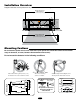
INTERIOR TOP OF
TRANSMITTER
12Vdc source
Transmitter/Receiver Connections
Wires from Photo Beams
INTERIOR TOP OF
RECEIVER
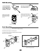
TAMPER
6
7
1 2 3 4 5 6 7
POWER
ALARM
+ –
1 2 6 7
To + Pos Terminal of Battery
To - Neg Terminal of Battery
1. Connect 1 and 2 power terminals
of the transmitter to the 1 and 2
power terminals of the receiver.
2. Connect 1 and 2 power terminals
of the Receiver OR Transmitter to
the battery.
3. Connect 3 and 5 terminals of the
receiver to the COM and SAFETY
terminals on the control board.