
Installation Guide


9
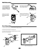
1. With the POWER connected and the
RECEIVER and TRANSMITTER covers
removed adjust the horizontal pivot,
and the vertical adjustment screw using
the built-in viewer. Look through the
viewnder on either side and adjust to put
the opposite sensor in the middle of the
cross-hairs in the view nder. The GOOD
LED should be on. (Adjust the light axis
until the indication lamp is on.)
The brighter the LEVEL (green) LED the
more precise the alignment of the beams.
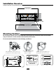
Beam Interruption Time Adjustment
Adjusts the amount of time between the beam being broken and the
normally open relay closing. Adjust time adjustment dial from (1) detecting
fast moving objects to (5) detecting slow moving objects depending on
your type of application and environment.
The factory setting is set to 1 to detect fast moving objects.
Beam Alignment
Adjusting Optical Axis with the Viewnder
If you have a voltmeter, the best method of adjusting the optical axis
is to measure the signal level at the test probe points.
1. Insert the voltmeter probes into the test points on the side of the re-
ceiver.
2. Adjust the horizontal angle and vertical angle until the voltage is at
maximum.
3. If a voltage of 1.2v or above cannot be reached, the transmitter and/or
receiver should be readjusted.
Adjusting Optical Axis with a Voltmeter
1
Fast Moving
Objects
5
Slow Moving
Objects
POWER
ALARM
LEVEL
GOOD
Close-up of
viewfinder with
reflection centered.
Vertical
Adjustment
Screw
RAISE LOWER
Horizontal
Adjustment
Bracket
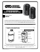
RECEIVER INDICATORS
GOOD LEVEL ALARM
RECEIVER
GOOD LED (green) • Use when adjusting bean alignment. ON when beams
are aligned.
LEVEL LED (green) • ON indicates receiving signal. Brightness varies, de-
pending on beam alignment.
ALARM LED (red) • ON indicates beam blocked. Use when setting response
time.
TRANSMITTER INDICATOR
POWER
TRANSMITTER
POWER LED (green)
• ON when when light
beam is transmitting.
+ –
LEVEL
Voltmeter
test points
Voltmeter
1
2
3
4
5
R
E
S
P
O
N
S
E
T
I
M
E