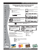
OPERATION AND PARTS MANUAL SERIES MODEL MTX-70 TAMPING RAMMER (HONDA GX100UKRBF GASOLINE ENGINE) Revision #5 (01/04/08) To find the latest revision of this publication, visit our website at: www.multiquip.com THIS MANUAL MUST ACCOMPANY THE EQUIPMENT AT ALL TIMES.
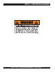
MTX-70 — PROPOSITION 65 WARNING PAGE 2 — MTX-70 — OPERATION AND PARTS MANUAL — REV.
NOTES MTX-70 — OPERATION AND PARTS MANUAL — REV.
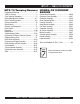
MTX-70 — TABLE OF CONTENTS MTX-70 Tamping Rammer HONDA GX100UKRBF Proposition 65 Warning ........................................... 2 ENGINE Table Of Contents ................................................... 4 Parts Ordering Procedures ..................................... 5 Safety Message Alert Symbols ............................ 6-7 Rules For Safe Operation .................................... 8-9 General Information .............................................. 10 Specifications ...................
MTX-70 — TABLE OF CONTENTS www.multiquip.com PARTS ORDERING PROCEDURES Ordering parts has never been easier! Choose from three easy options: Effective: January 1st, 2006 Best Deal! Order via Internet (Dealers Only): If you have an MQ Account, to obtain a Username and Password, E-mail us at: parts@multiquip.com.
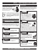
MTX-70 — SAFETY MESSAGE ALERT SYMBOLS FOR YOUR SAFETY AND THE SAFETY OF OTHERS! Safety precautions should be followed at all times when operating this equipment. Failure to read and understand the Safety Messages and Operating Instructions could result in injury to yourself and others.
MTX-70 — SAFETY MESSAGE ALERT SYMBOLS CAUTION Rotating Parts Hazards NEVER operate equipment with covers, or guards removed. Keep fingers, hands, hair and clothing away from all moving parts to prevent injury. CAUTION Accidental Starting Hazards ALWAYS place the ON/OFF switch in the OFF position when the rammer is not in use. CAUTION Eye and Hearing Hazards ALWAYS wear approved eye and hearing protection. DANGER Refueling Hazard NEVER refuel rammer when placed in truck bed with plastic liner.
MTX-70 — RULES FOR SAFE OPERATION DANGER Read this manual! Failure to follow instructions in this manual may lead to serious injury or even death! This equipment is to be operated by trained and qualified personnel only! This equipment is for industrial use only. The following safety guidelines should always be used when operating the MTX-70 Tamping Rammer: GENERAL SAFETY ■ DO NOT operate or service this equipment before reading this entire manual.
MTX-70 — RULES FOR SAFE OPERATION ■ ALWAYS stop the engine before servicing, adding fuel and oil. ■ NEVER run engine without air filter. Severe engine may occur. ■ ALWAYS service air cleaner frequently to prevent carburetor malfunction. ■ ALWAYS check the machine for loosened threads or bolts before starting. ■ ALWAYS be sure the operator is familiar with proper safety precautions and operations techniques before using rammer. ■ ALWAYS store equipment properly when it is not being used.
MTX-70 — GENERAL INFORMATION Definition of Tamping Rammer The Mikasa MTX-70 tamping rammer is a powerful compacting tool capable of applying a tremendous force in consecutive impacts to a soil surface. Its applications include soil compacting for road, embankments and reservoirs as well as backfilling for gas pipelines, water pipelines and cable installation work. CAUTION Handle Operation Before starting operation check the lifting handle to: 1. Make sure that there is no damage on the bolts.
MTX-70 — SPECIFICATIONS Table 1. MTX-70 Rammer Specifications Overall Height 39.37 in. (1000 mm) Overall Width 13.78 in (350 mm) Over Length 31.02 in (788 mm) Shoe Size 13.4 x 11.2 (340 x 285 mm) Fuel Tank Capacity 3.2 qt. (3 liters) Lubrication Oil Capacity 0.8 quart (0.75 liter) No. of Impacts Per Second 10.7 - 11.5 Impact Force 2,855 lb (12.7 kN) Impact Plate Stroke 2 -3.15 in (50 - 80 mm) Operating Weight 165.34 lbs. (75 kg) Table 2.
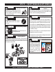
MTX-70 — CONTROLS AND COMPONENTS 3 10 2 4 1 5 9 6 11 7 12 13 8 Figure 1. MTX-70 Rammer Figure 1 shows the location of the controls and components for the MTX-70 Tamping Rammer. The functions of each control is described below: 1. Combination (Throttle) Lever – Used to adjust engine speed (rpm). Move lever forward (SLOW) to reduce engine speed, move lever back toward operator (FAST) to increase speed. Always operate the rammer at full speed (rpm). 2.
MTX-70 — BASIC ENGINE Figure 1A. Engine Controls and Components (Honda GX100) INITIAL SERVICING The engine (Figure 1A) must be checked for proper lubrication and filled with fuel prior to operation. Refer to the manufacturers Engine manual for instructions & details of operation and servicing. Choke Lever –Used when starting the engine. Normally used in cold weather conditions. In cold weather turn the choke lever to the fully closed position, in warm weather set choke lever half way or completely open.
MTX-70 — OPERATION This section is intended to assist the operator with the initial start-up of the MTX-70 Tamping Rammer. It extremely important that this section be read carefully before attempting to operate the rammer. DO NOT use your rammer until this section is thoroughly understood. CAUTI CAUTION Engine 1. Fill the fuel tank (Figure 3) with unleaded gasoline. At the same time, check the engine oil and make it a habit to replenish it often (Figure 4).
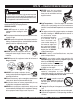
MTX-70 — OPERATION Inspection 1 . Check all nuts, bolts fasteners for tightness. Retighten as necessary. 3. Grip the starter rope handle (Figure 7 handle and pull it until you feel a slight resistance. Then pull sharply and quickly. Return the handle to the starter case before releasing. 2. Clean any dirt from the recoil starter and foot pedestal. Wipe the entire unit clean before operating. 3. Replace any missing or damaged Safety Operation decals. 4. Adjust height of handle.
MTX-70 — OPERATION Operation Stopping The Engine 1. To start the rammer tamping action, move the throttle lever (Figure 8) quickly from IDLE to the START ( ) position. DO NOT move the throttle lever slowly as this may cause damage to the clutch or spring. Normal Shutdown 1. Move throttle lever quickly from the START to IDLE position (Figure 9) and run the engine for three minutes at low speed. After the engine cools, move the throttle lever to the STOP position (Figure 10).
MTX-70 — MAINTENANCE Maintenance Perform the scheduled maintenance procedures as indicated: DAILY ■ Thoroughly remove dirt and oil from the engine and control area. ■ Clean or replace the air cleaner elements as necessary. Check and retighten all fasteners as necessary. ■ Check the spring box and bellows for oil leaks. Repair or replace as needed. EVERY 50 HOURS ■ Remove the fuel filter cap and clean the inside of the fuel tank (Figure 11).
MTX-70 — TROUBLESHOOTING GUIDE TABLE 4. ENGINE TROUBLESHOOTING SYMPTOM POSSIBLE PROBLEM SOLUTION Difficult to start Fuel is available but spark plug will not ignite. (Power available at high tension cable). Fuel is available but spark plug will not ignite. (Power NOT available at high tension cable). Fuel is available and spark plug ignites (compression normal). Fuel is available and spark plug ignites (compression low). Low compression. Ignition plug being bridge? Check ignition system.
MTX-70 — TROUBLESHOOTING GUIDE ENGINE TABLE 4. ENGINE TROUBLESHOOTING (continued) SYMPTOM POSSIBLE PROBLEM SOLUTION Operation not satisfactory Rotational speed fluctuates. Recoil star ter not working properly. Governor adjustment improper? Adjust governor to correct lever. Governor spring defective? Clean or replace ignition. Fuel flow erratic? Check fuel line. Air taken in through suction line? Check suction line. Dust in rotating par t? Clean recoil star ter assembly.
MTX-70—EXPLANATION OF PARTS SECTION REMARKS The following section explains the different symbols and remarks used in the Parts section of this manual. Use the help numbers found on the back page of the manual if there are any questions. The contents and part numbers listed in the parts section are subject to change without notice. Multiquip does not guarantee the availibility of the parts listed. * * Numbers Used - Item quantity can be indicated by a number, a blank entry, or A/R.
MTX-70— SUGGESTED SPARE PARTS MTX-70 RAMMER 1 TO 3 UNITS WITH HONDA GX100UKRBF ENGINE Qty. P/N Description 1 ......... 956100062 ....... THROTTLE WIRE 3 ......... 366010070 ....... SECONDARY ELEMENT, AIR CLEANER 3 ......... 366010080 ....... PRIMARY ELEMENT, AIR CLEANER 1 ......... 366900020 ....... CAP, FUEL TANK W/ STRAP 2 ......... 16910Z4ES21 .. FILTER, IN-LINE FUEL 3 ......... 9805655757 ..... SPARK PLUG 1 ......... 959300770 ....... STRAINER, FUEL TANK 1 ......... 28462Z0DV02 ..
MTX-70— NAMEPLATE AND DECALS 1 NAME PLATE AND DECALS 4 7 NPA-0000 ? ? ? ? ? ? ? NPA-1245 2 3 5 STOP NPA-0000 NPA-0000 6 11 MODEL SERIAL NO. A (DECAL SET) 8 MTX series RAMMER quick manual Engine Oil Use SAE 10W/30,SE or higher grade motor oil RAMMING CYLINDER OIL Use SAE 10W/30,SF or higher grade moter oil Fuel Use normal quality gasoline PAGE 22 — MTX-70 — OPERATION AND PARTS MANUAL — REV.
MTX-70— NAMEPLATE AND DECALS NAME PLATE AND DECALS NO PART NO PART NAME QTY. REMARKS A 920900040 DECAL SET ..................................... 1.......... INCLUDES ITEMS W/ # 1# DECAL: OPERATION 1 2# DECAL: AIR CLEANER 1 3# DECAL: LEVER OPERATION 1 4# DECAL: MAX SPEED 1 5# DECAL: MACHINE STOP 1 6# DECAL: EC NOISE REQ 1 7# DECAL: ANTI-VIB HANDLE 1 8 920212540 QUICK MANUAL 1 11 DECAL: NAMEPLATE ...................... 1.......... CONTACT MQ PARTS DEPT W/ SERIAL NO. MTX-70 — OPERATION AND PARTS MANUAL — REV.
MTX-70 — CRANKCASE AND ENGINE ASSY. CRANKCASE AND ENGINE ASSY.
MTX-70 — CRANKCASE AND ENGINE ASSY. CRANKCASE AND ENGINE ASSY. NO. 1 2$ 3 4 5 6 7 9 10 11 12 13 14 15 16 17 19 20 21 23 24 25-1 25-2 26 28 29 31 32-1 32-2 33 34 35 36 36-1# 36-2# 36-3# 36-4# 36-5# 36-7# 36-8# 36-9# 37 38 39 40 41 PART NO.
MTX-70 — CRANKCASE AND ENGINE ASSY. CRANKCASE AND ENGINE ASSY.
MTX-70 — CRANKCASE AND ENGINE ASSY. CRANKCASE AND ENGINE ASSY. NO. PART NO.
MTX-70 — GUIDE CYLINDER AND SPRING ASSY. GUIDE CYLINDER AND FOOT ASSY. 2 32 1 20 3 9 22 21 24 12 8 14 27 18 17 28 25 29 26 13 15 16 23 29 9 27 28 25 26 7 4 6 5-2 5-1 24 31 51 PAGE 28 — MTX-70 — OPERATION AND PARTS MANUAL — REV.
MTX-70 — GUIDE CYLINDER AND SPRING ASSY. GUIDE CYLINDER AND FOOT ASSY. NO. PART NO.
MTX-70 — FOOT ASSY. FOOT ASSY. 2 3 6 2 3 1 4 5 PAGE 30 — MTX-70 — OPERATION AND PARTS MANUAL — REV.
MTX-70 — FOOT ASSY. FOOT ASSY. NO. PART NO. 1 366910020 2 022711214 3 030212300 4 009110034 5 009110035 6 363343390 PART NAME FOOT ASSY 285 NYLON NUT M12 WASHER, LOCK M12 BOLT, SQUARE NECK 12X65 BOLT, SQUARE NECK 12X95 GRIP HANDLEBAR ON NUT M10 7 QTY. 1 4 4 2 2 1 REMARKS MTX-70 — OPERATION AND PARTS MANUAL — REV.
MTX-70 — TANK AND HANDLE ASSY. TANK AND HANDLE ASSY. 9 10 54 51 53 56 22 14 15 16 A 18 17 3 55 12 11-2 11-1 4-1 4-2 6 43 5 41 42 12 11-2 11-1 13 7 20 19 A 43 101 11-2 11-1 103 101 20 102 4-2 4-1 101 104 41 42 106 1 2-2 101 2-1 PAGE 32 — MTX-70 — OPERATION AND PARTS MANUAL — REV.
MTX-70 — TANK AND HANDLE ASSY. TANK AND HANDLE ASSY. NO. PART NO.
MTX-70 — COMBINATION LEVER ASSY. COMBINATION LEVER ASSY. PAGE 34 — MTX-70 — OPERATION AND PARTS MANUAL — REV.
MTX-70 — COMBINATION LEVER ASSY. COMBINATION LEVER ASSY. NO. PART NO. A 366900030 B 956200100 * 956200100 1 $ * 2 $ 366010180 * 3 366010190 * 366010200 4 * 5 366010210 * 6 $ 366010220 * 020408050 7 * 8 959407650 * 9 $ 366010260 * 956100062 10 * 11 $ 094010051 * 094010052 12 $ * 13 $ 050200150 * 14 $ 050200110 * PART NAME QTY. REMARKS LEVER AY W/T, WIRE ............................ 1 .........
MTX-70 — TOOLS TOOLS PAGE 36 — MTX-70 — OPERATION AND PARTS MANUAL — REV.
MTX-70 — TOOLS TOOLS NO. 1 2 3 4 PART NO. 981010400 983010060 983910090 009110044 5 6 7 983910020 983010040 983910010 PART NAME CLUTCH PULLER A CLUTCH MOUNTER PISTON ROD HOLDER SOCKET HEAD BOLT 8X50 (FULL THREAD) CRANK GEAR REMOVER CLUTCH PULLER B SPRING CYLINDER REMOVER PISTON END REMOVER QTY. 1 1 1 REMARKS 2 1 1 1 MTX-70 — OPERATION AND PARTS MANUAL — REV.
HONDA GX100UKRBF ENGINE — CYLINDER BARREL ASSY. CYLINDER BARREL ASSY. PAGE 38 — MTX-70 — OPERATION AND PARTS MANUAL — REV.
HONDA GX100UKRBF ENGINE — CYLINDER BARREL ASSY. CYLINDER BARREL ASSY. NO. PART NO. 1 12000Z0DV00 2 12201Z0D305 * 12204Z0D305 3 * 5 12311Z0D000 6 12355Z0D000 7 12365Z0D000 8 15571Z0DV71 9 15572ZM7000 10 15721Z0DV70 11 90014952000 12 91202KJ9003 * 13 93500030050A 14 9805655757 15 15171Z0DV00 16 90008ZM7000 PART NAME QTY. REMARKS BARREL ASSY., CYLINDER ..... 1 ...................... INCLUDES ITEMS W/ * GUIDE ASSY., EX VALVE (O.S.)1 GUIDE, INLET VALVE (O.
HONDA GX100UKRBF ENGINE — CRANKCASE COVER ASSY. CRANKCASE COVER ASSY. MTX-70 — EH12-2D ROBIN ENGINE— CRANKSHAFT AND PISTON PAGE 40 — MTX-70 — OPERATION AND PARTS MANUAL — REV.
HONDA GX100UKRBF ENGINE — CRANKCASE COVER ASSY. CRANKCASE COVER ASSY. NO. PART NO. 1 11300Z0D409 3 15600ZM7003 4# 15625ZE1003 5 16510ZL8000 * 9 16531ZE1000 * 10 16541Z0D000 11 90121952000 12 90131ZE1000 13 90451ZE1000 * 14 90601ZE1000 15 90602ZE1000 * 16 91202KJ9003 * 17 9410106800 * 18 9425108000 19 9430108200 21 91001Z0DV01 * 23 11511Z0DV10 24 91231891003 26 9430306100 27 957010804500 28 934021004000 PART NAME QTY. REMARKS COVER ASSY., CRANK CASE .. 1 ......................
HONDA GX100UKRBF ENGINE — CRANKSHAFT ASSY. CRANKSHAFT ASSY. 3 f 8 16.8 85.3 6 PAGE 42 — MTX-70 — OPERATION AND PARTS MANUAL — REV.
HONDA GX100UKRBF ENGINE — CRANKSHAFT ASSY. CRANKSHAFT ASSY. NO. 3 6 * PART NO. 13310Z0DV70 91001Z0DV01 PART NAME QTY. REMARKS CRANK SHAFT COMP. ............. 1 ...................... INCLUDES ITEM W/ * BEARING, RADIAL BALL 2 MTX-70 — OPERATION AND PARTS MANUAL — REV.
HONDA GX100UKRBF ENGINE — PISTON CONNECTING ROD ASSY. PISTON CONNECTING ROD ASSY. PAGE 44 — MTX-70 — OPERATION AND PARTS MANUAL — REV.
HONDA GX100UKRBF ENGINE — PISTON CONNECTING ROD ASSY. PISTON CONNECTING ROD ASSY. NO. PART NO. PART NAME QTY. REMARKS 1 13010Z0D003 RING SET, PISTON 1 2 13101Z0D000 PISTON 1 3 13111ZE0000 PISTON PIN 1 4 13200Z0D000 CONNECTING ROD ASSY. ....... 1 ...................... INCLUDES ITEM W/ * 4 13200Z0D305 CONNECTING ROD ASSY. ....... 1 ...................... UNDERSIZE, INCLUDES ITEM W/ * 5 90001ZM7000 CONNECTING ROD BOLT 2 * 6 90551ZE0000 CLIP, PISTON PIN 13MM 2 MTX-70 — OPERATION AND PARTS MANUAL — REV.
HONDA GX100UKRBF ENGINE — CAMSHAFT ASSY. CAMSHAFT ASSY. PAGE 46 — MTX-70 — OPERATION AND PARTS MANUAL — REV.
HONDA GX100UKRBF ENGINE —CAMSHAFT ASSY. CAMSHAFT ASSY. NO. PART NO. 1 14320Z0D010 2 14324Z0D000 3 14400Z0D003 4 14431Z0D000 5 14441Z0D000 6 14461ZL8000 7 14711Z0D000 8 14721Z0D000 9 14751Z0D000 10 14771ZM3010 11 90012333000 12 90206001000 13 91301ZM0V31 14 12209KT7013 PART NAME QTY. PULLEY, COMP.
HONDA GX100UKRBF ENGINE — RECOIL STARTER ASSY. RECOIL STARTER ASSY. PAGE 48 — MTX-70 — OPERATION AND PARTS MANUAL — REV.
HONDA GX100UKRBF ENGINE — RECOIL STARTER ASSY. RECOIL STARTER ASSY. NO. 1 2 * 3 * 4 * 5 * 6 * 7 * 8 * 9 * 10 * 11 * 12 * 13 PART NO. 28400Z0DV03ZA 28410Z0DV02ZA 28421Z0DV02 28422ZG0W02 28433ZG0W02 28441ZW6003 28442ZH8003 28461ZH8003 28462Z0DV02 28467Z0DV02 28468Z0DV02 90003ZH8003 957010600800 PART NAME QTY. REMARKS RECOIL STARTER ASSY .................. 1............... INCLUDES ITEMS W/ * CASE COMP.
HONDA GX100UKRBF ENGINE — FAN COVER ASSY. FAN COVER ASSY. PAGE 50 — MTX-70 — OPERATION AND PARTS MANUAL — REV.
HONDA GX100UKRBF ENGINE — FAN COVER ASSY. FAN COVER ASSY. NO. PART NO. 1 19610Z0DV00ZB 3 90014952000 PART NAME QTY. FAN COVER CP. 1 BOLT, FLANGE 6X14 (CT200) 4 REMARKS MTX-70 — OPERATION AND PARTS MANUAL — REV.
HONDA GX100UKRBF ENGINE — CARBURETOR ASSY. CARBURETOR ASSY. 11 18 9 2 37 17 16 10 35 15 31 19 20 32 21 38 36 38 34 24 4 28 26 29 30 5 12 7 31 23 25 27 42 40 39 40 33 6 1 3 8 14 13 25 PAGE 52 — MTX-70 — OPERATION AND PARTS MANUAL — REV.
HONDA GX100UKRBF ENGINE — CARBURETOR ASSY. CARBURETOR ASSY. NO. PART NO.
HONDA GX100UKRBF ENGINE — AIR CLEANER ASSY. AIR CLEANER ASSY. 8 14 10 11 PAGE 54 — MTX-70 — OPERATION AND PARTS MANUAL — REV.
HONDA GX100UKRBF ENGINE — AIR CLEANER ASSY. AIR CLEANER ASSY. NO. 8 10 11 14 PART NO. 17228Z0DV01 90042Z4ES30 9405005000 17410Z4ES30 PART NAME PACKING, AIR CLEANER STUD BOLT 5X95 FLANGE NUT 5MM ELBOW, AIR CLEANER QTY. 1 2 2 1 REMARKS MTX-70 — OPERATION AND PARTS MANUAL — REV.
HONDA GX100UKRBF ENGINE — MUFFLER ASSY. MUFFLER ASSY. PAGE 56 — MTX-70 — OPERATION AND PARTS MANUAL — REV.
HONDA GX100UKRBF ENGINE — MUFFLER ASSY. MUFFLER NO. 1 2 3 4 5 6 ASSY. PART NO. 18310Z0DV20 18321Z0DV20 18381Z0D000 90014952000 90048Z0DV00 90343ZE6000 PART NAME QTY. MUFFLER COMP. 1 MUFFLER PROTECTOR 1 GASKET, MUFFLER 1 VOLT, FLANGE 6X14 (CT200) 3 STUD BOLT 5X78 2 NUT, SELF-LOCK 6MM 2 REMARKS MTX-70 — OPERATION AND PARTS MANUAL — REV.
HONDA GX100UKRBF ENGINE — FLYWHEEL IGNITION ASSY. FLYWHEEL IGNITION ASSY. 3 7 7 12 4 11 1 10 9 PAGE 58 — MTX-70 — OPERATION AND PARTS MANUAL — REV.
HONDA GX100UKRBF ENGINE — FLYWHEEL IGNITION ASSY. FLYWHEEL IGNITION ASSY. NO. 1 3 4 7 9 10 11 12 * PART NO. 13331ZM7000 30564ZA5000 31110Z0D003 90022888010 9405012000 28451Z0DV02 30500Z0DV02 30700Z0DV01 PART NAME QTY. REMARKS WOODRUFF KEY 25X18 1 GROMMET, CORD 1 FLYWHEEL COMP. 1 FLANGE BOLT 6X20 2 FLANGE NUT M12 1 STARTER PULLEY 1 IGNITION COIL ASSY ............... 1 ...................... INCLUDES ITEMS W/ * TERMINAL ASSY. 1 MTX-70 — OPERATION AND PARTS MANUAL — REV.
HONDA GX100UKRBF ENGINE — CONTROL ASSY. CONTROL ASSY. 3 17 5 20 11 15 10 4 9 19 12 6 8 8 PAGE 60 — MTX-70 — OPERATION AND PARTS MANUAL — REV.
HONDA GX100UKRBF ENGINE — CONTROL ASSY. CONTROL ASSY. NO. PART NO. 3 16555Z0DV00 4 16561Z0DV00 5 16562Z0DV00 6 16594883010 * 8 90014952000 9 90015ZE5010 10 90605230000 * 11 92301050200A * 93500040060H 12 * 15 9405006000 17 16550Z0DV01 19 16500Z4ES30 20 9400105000 * PART NAME QTY. REMARKS GOVERNOR ROD 1 GOVERNOR SPRING 1 SPRING, THROTTLE RETURN 1 HOLDER, WIRE 1 VOLT, FLANGE 6X14 (CT200) 2 BOLT, GOVERNOR ARM 1 CIR CLIP 1 BOLT 5X20 1 SCREW 4X6 1 FLANGE NUT 6MM 1 GOVERNOR ARM 1 CONTROL ASSY ..................
HONDA GX100UKRBF ENGINE — LABELS ASSY. LABELS ASSY. PAGE 62 — MTX-70 — OPERATION AND PARTS MANUAL — REV.
HONDA GX100UKRBF ENGINE — LABELS ASSY. LABELS ASSY. NO. PART NO. 2 87521Z0DV01 4 87528Z0D000 6 87601Z4ES30 14 89216130690 PART NAME LABEL, TRADE MARK MARK, CHOKE MARK, TYPE (KRBF) WRENCH, SPARK PLUG QTY. 1 1 1 1 REMARKS MTX-70 — OPERATION AND PARTS MANUAL — REV.
TERMS AND CONDITIONS OF SALE — PARTS PAYMENT TERMS 5. Parts must be in new and resalable condition, in the original Multiquip package (if any), and with Multiquip part numbers clearly marked. 6. The following items are not returnable: Terms of payment for parts are net 30 days. FREIGHT POLICY All parts orders will be shipped collect or prepaid with the charges added to the invoice. All shipments are F.O.B. point of origin.
NOTES MTX-70 — OPERATION AND PARTS MANUAL — REV.
OPERATION AND PARTS MANUAL HERE’S HOW TO GET HELP PLEASE HAVE THE MODEL AND SERIAL NUMBER ON-HAND WHEN CALLING UNITED STATES Multiquip Corporate Office 18910 Wilmington Ave. Tel. (800) 421-1244 Carson, CA 90746 Fax (800) 537-3927 Contact: mq@multiquip.