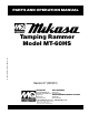
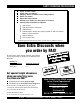
PARTS AND OPERATION MANUAL PARTS AND OPERATION MANUAL © COPYRIGHT 2001, MULTIQUIP INC. Tamping Rammer Model MT-60HS Revision #7 (03/02/01) MULTIQUIP INC.. PARTS DEPARTMENT: 18910 WILMINGTON AVE. 800-427-1244 CARSON, CALIFORNIA 90746 FAX: 800-672-7877 SERVICE DEPARTMENT/TECHNICAL ASSISTANCE: 310-537-3700 800-421-1244 800-478-1244 FAX: 310-537-3927 FAX: 310-631-5032 E-mail:mq@multiquip.com • www:multiquip.
PAGE 2 — MT-60HS — PARTS & OPERATION MANUAL — REV.
HERE'S HOW TO GET HELP PLEASE HAVE THE MODEL AND SERIAL NUMBER ON-HAND WHEN CALLING PARTS DEPARTMENT 800-427-1244 or 310-537-3700 FAX: 800-672-7877 or 310-637-3284 SERVICE DEPARTMENT/TECHNICAL ASSISTANCE 800-478-1244 or 310-537-3700 FAX: 310- 537-4259 WARRANTY DEPARTMENT 888-661-4279, or 310-661-4279 FAX: 310- 537-1173 MAIN 800-421-1244 or 310-537-3700 FAX: 310-537-3927 MT-60HS — PARTS & OPERATION MANUAL — REV.
TABLE OF CONTENTS Here's How To Get Help ........................................ 3 Table Of Contents ................................................. 4 Parts Ordering Procedures ................................... 5 Rules For safe Operation ..................................6-7 Operation and Safety Decals ................................ 8 General Information .............................................. 9 MT-60HS Specification ........................................................
PARTS ORDERING PROCEDURES n n n n n n n Dealer account number Dealer name and address Shipping address (if different than billing address) Return fax number Applicable model number Quantity, part number and description of each part Specify preferred method of shipment: • • • • UPS Ground UPS Second Day or Third Day* UPS Next Day* Federal Express Priority One (please provide us with your Federal Express account number)* • • Airborne Express* Truck or parcel post *Normally shipped the same day the order
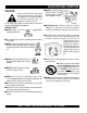
RULES FOR SAFE OPERATION CAUTION: Failure to follow instructions in this manual may lead to serious injury or even death! This equipment is to be operated by trained and qualified personnel only! This equipment is for industrial use only. The following safety guidelines should always be used when operating the MT-60HS Tamping Rammer: GENERAL SAFETY ■ DO NOT operate or service this reading this entire manual. equipment before ■ This equipment should not be operated by persons under 18 years of age.
RULES FOR SAFE OPERATION ■ NEVER Run engine without air filter. Severe engine may occur. Transporting ■ Always shutdown engine before transporting. ■ Always service air cleaner frequently to prevent carburetor malfunction. ■ Tighten fuel tank cap securly and close fuel cock to prevent fuel from spilling. ■ Always be sure the operator is familiar with proper safety precautions and operations techniques before using rammer. ■ Drain fuel when transporting rammer over long distances or bad roads.
OPERATION AND SAFETY DECALS PAGE 8 — MT-60HS — PARTS & OPERATION MANUAL — REV.
MT-60HS — PARTS & OPERATION MANUAL — REV.
GENERAL INFORMATION Definition of Tamping Rammer The Mikasa MT-60HS Tamping Rammer is a powerful compacting tool capable of applying a tremendous force in consecutive impacts to a soil surface. Its applications include soil compacting for backfilling for gas pipelines, water pipelines and cable installation work. The impact force of the MT-60HS levels and uniformly compacts voids between soil particles to increase dry density. Circular motion is converted to create impact force.
SPECIFICATIONS Table1. MT-60HS Rammer Specifications MODEL MT-60HS U.S. (metric) Overall Height 39.4 in. (1,000 mm) Overall Width 15.4 in. (390 mm) Over Length 27.6 in. (700 mm) Shoe Size 10.4 X 13.4 in. (265 X 340 mm) Blows/minute 675 Impact Force 2,610 lbs./blow (1,179 kg/blow) Clutch Automatic Centrifugal Operating Weight 129 lbs. (58.5 kg) Table 2. ROBIN EC-08GH Engine Specifications MODEL ROBIN EC-08GH ENGINE Type Air-Cooled 2 Stroke Gasoline Engine Piston Displacement 1.12 cu.
MT-60HS — CONTROLS AND COMPONENTS Figure 1. MT-60HS Rammer Figure 1 shows the location of the controls and components 8. Foot– Laminated wood with tempered steel plate for for the MT-60HS Tamping Rammer. The functions of each control is described below: 1. Throttle Lever – Controls engine speed and the tamping action of the rammer. 2. Engine Stop Switch – Controls the starting and stopping of the engine. Switch must be in the "ON" position when starting the engine. 3.
MT-60HS — OPERATION This section is intended to assist the operator with the initial start-up of the MT-60HS Tamping Rammer. It extremely important that this section be read carefully before attempting to operate the rammer. CAUTION: Failure to understand the operation of the MT60HS Tamping Rammer could result in severe damage to the rammer or personal injury. DO NOT use your rammer until this section is thoroughly understood.
MT-60HS — OPERATION Table 3. Motor Oil Grade Season or Temperature Grade of motor oil (higher than MS class) Spring, Summer or Autumn + 1 2 0 ° F to + 1 5 ° F SAE 30 Winter +40° F to +15° F SAE 30 Below +15° F SAE 10W-30 2. Set the engine ON/OFF switch (Figure 6) to the "ON" position (start). Inspection 1. Check all nuts, bolts fasteners for tightness. Retighten as necessary. 2. Clean any dirt from the recoil starter and foot pedestal. Wipe the entire unit clean before operating. 3.
MT-60HS — OPERATION 7. If the carburetor is flooded or the crankcase is loaded with excess fuel, open the drain plug as shown in (Figure 8) and drain out excess fuel. Figure 8. Drain Plug Stopping The Engine Normal Shutdown 1. Move throttle lever quickly from the FULL OPEN to IDLE position (Figure 10) and run the engine for three minutes at low speed. After the engine cools, turn the engine start/stop switch to the “OFF” position (Figure 5) until engine comes to a complete stop. 2.
MT-60HS — MAINTENANCE Maintenance Perform the scheduled maintenance procedures as indicated: DAILY ■ Thoroughly remove dirt and oil from the engine and control area. Clean or replace the air cleaner elements as necessary. Check and retighten all fasteners as necessary. Check the spring box and bellows for oil leaks. Repair or replace as needed. WEEKLY ■ Remove the fuel filter cap and clean the inside of the fuel tank. ■ Remove or clean the filter at the bottom of the tank.
MT-60HS — MAINTENANCE 2. Remove the bolts that secure the oil tank to the fuel tank, and drain all oil from the tank. 3. Remove cock holder, then clean strainer and cock holder in a kerosene solution. 4. Make sure every part is clean and dry, then reassemble oil tank. Fill oil tank with 2-stroke outboard motor oil (FB class) to the "H" level. FUEL AND OIL LINES ■ Check the fuel and oil lines regularly for damage and ensure that there are no leaks.
MT-60HS — TROUBLESHOOTING GUIDE TABLE 4. ENGINE TROUBLESHOOTING SYMPTOM POSSIBLE PROBLEM SOLUTION Difficult to start Fuel is available but spark plug will not ignite. (Power available at high tension cable). Fuel is available but spark plug will not ignite. (Power NOT available at high tension cable). Fuel is available and spark plug ignites (compression normal). Fuel is available and spark plug ignites (compression low ). Ignition plug being bridge? Check ignition system.
MT-60HS — TROUBLESHOOTING GUIDE ENGINE TABLE 4. ENGINE TROUBLESHOOTING (continued) SYMPTOM POSSIBLE PROBLEM SOLUTION Operation not satisfactory Rotational speed fluctuates. Recoil star ter not working properly. Governor adjustment improper? Adjust governor to correct lever. Governor spring defective? Clean or replace ignition. Fuel flow erratic? Check fuel line. Air taken in through suction line? Check suction line. Dust in rotating par t? Clean recoil star ter assembly.
MT-60HS — EXPLANATION OF CODE IN REMARKS COLUMN How to read the marks and remarks used in this parts book. Items Found In the “Remarks” Column Serial Numbers-Where indicated, this indicates a serial number range (inclusive) where a particular part is used. Model Number-Where indicated, this shows that the corresponding part is utilized only with this specific model number or model number variant.
MT-60HS — SUGGESTED SPARE PARTS MT-60HS — SUGGESTED SPARE PARTS MT-60HS Tamping Rammer MT-60HS Tamping Rammer 1 to 3 Units Qty. P/N Description 1 ......... 956300130 .......... THROTTLE LEVER 1 ......... 501302060 .......... THROTTLE WIRE 1 ......... 402010110 .......... SPRING, RETURN 3 ......... 354030030 .......... ELEMENT, YELLOW 3 ......... 354030040 .......... ELEMENT, GRAY 3 ......... 1573620101 ........ ELEMENT SET, ENGINE 3 ......... 0650140031 ........ SPARK PLUG 1 ......... 0430440033 .......
MT-60HS — NAMEPLATE AND DECALS NAMEPLATE AND DECALS PAGE 22 — MT-60HS — PARTS & OPERATION MANUAL — REV.
MT-60HS — NAMEPLATE AND DECALS NAME PLATE AND DECALS NO. 1 2 3 4 5 6 7 8 9 10 11 * * * * * * * * * PART NO. 920106460 920203980 920203290 920107000 920203540 920203990 920203330 920204370 920201950 DCLMT60H2 PART NAME QTY. REMARKS DECAL: MIKASA MARK 1 DECAL: ELEMENT SET 1 DECAL: READ OWNER'S MAN. 1 PLATE: SERIAL NO. ....................... 1 .....ORDER FROM MQ SER. DEPT. W/MODEL & S/N DECAL: PRE-CLEANER / MT-W 1 DECAL ENGINE R.P.
MT-60HS — CRANKCASE AND ENGINE ASSY. CRANKCASE AND ENGINE ASSY. PAGE 24 — MT-60HS — PARTS & OPERATION MANUAL — REV.
MT-60HS — CRANKCASE AND ENGINE ASSY. CRANKCASE AND ENGINE ASSY. NO. 1 2 3 4 5 6 7 8 9 10 16 17 18 19 20 21 25 26 27 30 31 32 33 34 35 36 39 40 40-1 40-2 40-3 40-4 40-5 41 42 43 44 45 46 48 49 50 51 60 61 62 63 64 65# 66# 67# 68# 69# 70 71 72 * * * * * PART NO.
MT-60HS — CYLINDER GUIDE AND FOOT ASSY. CYLINDER GUIDE AND FOOT ASSY. 100 EXCLUDES ITEMS 103, 105 & 106 PAGE 26 — MT-60HS — PARTS & OPERATION MANUAL — REV.
MT-60HS — CYLINDER GUIDE AND FOOT ASSY. CYLINDER GUIDE AND FOOT ASSY. NO. 61 62 63 64 65 66 67 68 69 70 71 73 74 75 76 77 78 82 83 84 85 86 87 88 89 90 100 101 102 103 104 105 106 107 108 109 110 112 113 * * * * * * * PART NO.
MT-60HS — TANK AND HANDLE ASSY. TANK AND HANDLE ASSY. 21 211 PAGE 28 — MT-60HS — PARTS & OPERATION MANUAL — REV.
MT-60HS — TANK AND HANDLE ASSY. TANK AND HANDLE ASSY. NO. A 1 1 2 3 4 5 11 12 13 14 15 15 16 16 17 18 19 20 21 21-1# 21-2# 21-3# 22 23 24 25 30 31 31-1 32 32-1 35 36 37 38 39 40 41 42 45 47 PART NO.
MT-60HS — TANK AND HANDLE ASSY. TANK AND HANDLE ASSY. 21 211 PAGE 30 — MT-60HS — PARTS & OPERATION MANUAL — REV.
MT-60HS — TANK AND HANDLE ASSY. TANK AND HANDLE ASSY. NO. 53 54 55 58 59 60 60 62 62-1 63 64 65 66 67 68 69 70 71 72 PART NO. 353448990 353449001 353449010 353030080 091005015 031105080 952405970 353449240 353450220 954403030 1616391008 1616391608 5806113040 353910020 355450600 361910040 091005025 031105080 022610505 PART NAME QTY. REMARKS PACKING, OIL TANK CAP 1 STRAINER, OIL TANK 1 ................ REPLACES 353449000 STRAP, OIL TANK 2 WELL NUT 1 SCREW 5x 5 1 PW M5 1 WASHER 6.
ROBIN EC-08GH ENGINE — CRANKCASE AND CYLINDER ASSY. CRANKCASE AND CYLINDER ASSY. 115 PAGE 32 — MT-60HS — PARTS & OPERATION MANUAL — REV.
ROBIN EC-08GH ENGINE — CRANKCASE AND CYLINDER ASSY. CRANKCASE AND CYLINDER ASSY. NO. 10 30 35 36 40 41 50 95 105 115 140 145 146 170 180 190 200 510 850 * * * * * * * * PART NO. 5801056000 0440200020 0440200020 0440060010 0600200010 0600200020 0052606140 0011406450 0105060050 0105064940 0643109980 5809011000 0011308180 5801501800 0021706000 0030206150 0031006000 5801501400 1507520103 PART NAME QTY. REMARKS CRANK CASE CP ................................ 1 ............
ROBIN EC-08GH ENGINE — CRANKSHAFT AND PISTON ASSY. CRANKSHAFT AND PISTON ASSY. PAGE 34 — MT-60HS — PARTS & OPERATION MANUAL — REV.
ROBIN EC-08GH ENGINE — CRANKSHAFT AND PISTON ASSY. CRANKSHAFT AND PISTON ASSY. NO. 10 30 40 50 60 65 70 130 131 132 140 160 170 350 360 370 380 390 PART NO. 5802028000 0323049950 1292500103 0039310000 0030210250 0030206150 0323049950 5804010000 0043105080 0032005000 5514500100 0230230020 0173120010 5802500400 5802500600 5000008100 0565119990 0610120010 PART NAME QTY. REMARKS CRANK SHAFT 1 WOODRUFF KEY 1 SPACER 2 NUT ...................................................... 1 ............
ROBIN EC-08GH ENGINE — GOVERNOR ASSY. GOVERNOR ASSY. PAGE 36 — MT-60HS — PARTS & OPERATION MANUAL — REV.
ROBIN EC-08GH ENGINE — GOVERNOR ASSY. GOVERNOR ASSY. NO. 10 15 16 20 30 40 80 90 100 120 130 305 310 340 341 342 350 360 370 380 400 480 610 620 PART NO. 5804005000 5804500900 2266255008 1294220103 1054270111 1064280113 1294250111 1294210113 0140039980 0021706000 0032061500 0217060020 5804500800 5804500600 0230060090 0105050616 0200070010 0016506400 0021706000 0170069960 1294500103 402010110 0149060040 0020106050 PART NAME QTY. REMARKS GOVERNOR LEVER 1 BUSH 2 BUSH, NYLON .................................
ROBIN EC-08GH ENGINE — MUFFLER ASSY. MUFFLER ASSY. PAGE 38 — MT-60HS — PARTS & OPERATION MANUAL — REV.
ROBIN EC-08GH ENGINE — MUFFLER ASSY. MUFFLER ASSY. NO. 310 330 331 340 350 355 356 361 362 PART NO. 5803032000 5803033000 5803034000 1293500403 0170069960 0030206150 0031006000 00167061960 0031006000 PART NAME QTY. REMARKS MUFFLER 1 MUFFLER BRACKET A 1 MUFFLER BRACKET B 1 GASKET (MUFFLER) 1 U NUT 2 SPRING WASHER ............................... 6 ............REPLACES 0032006000 WASHER 4 BOLT (MUFFLER) 4 WASHER 2 MT-60HS — PARTS & OPERATION MANUAL — REV.
ROBIN EC-08GH ENGINE — CARBURETOR AND OIL PUMP ASSY. CARBURETOR AND OIL PUMP ASSY. PAGE 40 — MT-60HS — PARTS & OPERATION MANUAL — REV.
ROBIN EC-08GH ENGINE — CARBURETOR AND OIL PUMP ASSY. CARBURETOR AND OIL PUMP ASSY. NO. 210 250 700 705 706 710 716 720 730 731 732 733 740 745 750 760 765 PART NO. 5806111000 1616235308 5806113000 5806502300 0323039980 0011306250 0031520000 1616350101 5806501900 0119089970 0030208200 0031008000 5806502000 5806502100 5806502200 0566059980 0119059610 PART NAME QTY. REMARKS CARBURETOR ASSY ......................... 1 ............SEE CARBURETOR FIG.
ROBIN EC-08GH ENGINE — RECOIL STARTER AND BLOWER ASSY. RECOIL STARTER AND BLOWER ASSY. PAGE 42 — MT-60HS — PARTS & OPERATION MANUAL — REV.
ROBIN EC-08GH ENGINE — RECOIL STARTER AND BLOWER ASSY. RECOIL STARTER AND BLOWER ASSY. NO. 10 15 20 25 40 50 51 52 53 210 PART NO. 5805501200 5515500200 920100240 5809500701 0011106200 5805022000 0016706200 0031206000 0030206150 5805001000 220 230 850 0011006100 0011006140 0566000250 PART NAME QTY. REMARKS FAN COVER 1 GUIDE RUBBER 1 DECAL, (M-MARK) 1 LABEL, MODEL 1 BOLT ASSY 4 CYLINDER COVER CP 1 BOLT (CYLINDER) 2 WASHER 2 SPRING WASHER ............................... 2 ............
ROBIN EC-08GH ENGINE — AIR CLEANER ASSY. AIR CLEANER ASSY. 526 PAGE 44 — MT-60HS — PARTS & OPERATION MANUAL — REV.
ROBIN EC-08GH ENGINE — AIR CLEANER ASSY. AIR CLEANER ASSY. NO. 510 520 521 522 526 540 550 560 580 600 * * * PART NO. 1063273110 1573620101 1613261008 2263272008 0736439980 1293290103 1063500103 2363590303 0011306800 0030206150 PART NAME QTY. REMARKS AIR CLEANER ASSY ........................... 1 ............INCLS. ALL ITEMS W/ ELEMENT SET .................................... 1 ............
ROBIN EC-08GH ENGINE — CARBURETOR COMPONENTS ASSY. CARBURETOR COMPONENTS ASSY. PAGE 46 — MT-60HS — PARTS & OPERATION MANUAL — REV.
ROBIN EC-08GH ENGINE — CARBURETOR COMPONENTS ASSY. CARBURETOR COMPONENTS ASSY. NO. A 1 2 3 4 5 # 6 # 7 # 8 9 1 12 # 13 14 # 15 # 16 17 # 18 # 19 # 20 22 # 28 40 # 41 # 60 62 63 82 # 104 106 107 108 # * * * * * * * * * * * * * * * * * * * * * * * * * * * * * * * PART NO. PART NAME QTY. REMARKS 5806111000 CARBURETOR ASSY ......................... 1 ............INCLUDES ITEMS W/ 1616253508 THROTTLE VALVE .............................. 1 ............
ROBIN EC-08GH ENGINE — RECOIL STARTER COMPONENTS ASSY. RECOIL STARTER COMPONENTS ASSY. PAGE 48 — MT-60HS — PARTS & OPERATION MANUAL — REV.
ROBIN EC-08GH ENGINE — RECOIL STARTER COMPONENTS ASSY. RECOIL STARTER COMPONENTS ASSY. NO. A 1 2 3 4 5 6 7 11 13 35 49 * * * * * * * * * * * PART NO. 5805001000 5805004020 5805004030 5805011040 5805001030 5805004040 5805004110 5805004050 EC08A050311 5515005160 EC08A05038 5805011020 PART NAME QTY. REMARKS RECOIL STARTER ASSY .................... 1 ............INCLS. ALL ITEMS W/ SPIRAL SPRING 1 REEL 1 STARTER ROPE 1 STARTER HANDLE 1 RATCHET 1 FRICTION SPRING 1 RETURN SPRING 1 STARTER PULLEY ..............
ROBIN EC-08GH ENGINE — MAGNETO ASSY. MAGNETO ASSY. PAGE 50 — MT-60HS — PARTS & OPERATION MANUAL — REV.
ROBIN EC-08GH ENGINE — MAGNETO ASSY. MAGNETO ASSY. NO. 10 11 18 30 40 60 70 81 95 100 110 PART NO. 5807005010 5807007020 0851029960 0011105250 1507520103 0660000361 0043304100 0241069980 0659000010 0650140031 0655000140 PART NAME QTY. REMARKS FLYWHEEL 1 IGNITION COIL 1 VINYL PIPE 1 BOLT AND WASHER ASSY 2 CLAMP ................................................. 1 ............REPLACES 0566099950 STOP SWITCH ASSY (ON-OFF) 1 SCREW 4X10 2 GROMMET 1 SPARK PLUG CLIP .............................. 1 ............
TERMS AND CONDITIONS OF SALE — PARTS Effective: July 1, 2000 4. PAYMENT TERMS Terms of payment for parts are net 10 days. FREIGHT POLICY All parts orders will be shipped collect or prepaid with the charges added to the invoice. All shipments are F.O.B. point of origin. Multiquip’s responsibility ceases when a signed manifest has been obtained from the carrier, and any claim for shortage or damage must be settled between the consignee and the carrier. Freight is at the sender’s expense.
NOTE PAGE MT-60HS — PARTS & OPERATION MANUAL — REV.
PARTS AND OPERATION MANUAL HERE'S HOW TO GET HELP PLEASE HAVE THE MODEL AND SERIAL NUMBER ON-HAND WHEN CALLING PARTS DEPARTMENT 800-427-1244 or 310-537-3700 FAX: 800-672-7877 or 310-637-3284 SERVICE DEPARTMENT/TECHNICAL ASSISTANCE 800-478-1244 or 310-537-3700 FAX: 310- 537-4259 WARRANTY DEPARTMENT 888-661-4279, or 310-661-4279 FAX: 310- 537-1173 MAIN 800-421-1244 or 310-537-3700 FAX: 310-537-3927 MULTIQUIP INC.