
Information


DocID15818 Rev 11 99/178
STM32F20xxx Electrical characteristics
177
The test results are given in Table 41. They are based on the EMS levels and classes
defined in application note AN1709.
Designing hardened software to avoid noise problems
EMC characterization and optimization are performed at component level with a typical
application environment and simplified MCU software. It should be noted that good EMC
performance is highly dependent on the user application and the software in particular.
Therefore it is recommended that the user applies EMC software optimization and
prequalification tests in relation with the EMC level requested for his application.
Software recommendations
The software flowchart must include the management of runaway conditions such as:
• Corrupted program counter
• Unexpected reset
• Critical Data corruption (control registers...)
Prequalification trials
Most of the common failures (unexpected reset and program counter corruption) can be
reproduced by manually forcing a low state on the NRST pin or the Oscillator pins for 1
second.
To complete these trials, ESD stress can be applied directly on the device, over the range of
specification values. When unexpected behavior is detected, the software can be hardened
to prevent unrecoverable errors occurring (see application note AN1015).
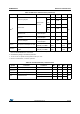
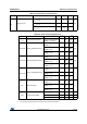
Table 41. EMS characteristics
Symbol Parameter Conditions
Level/
Class
V
FESD
Voltage limits to be applied on any I/O pin to
induce a functional disturbance
V
DD
= 3.3 V, LQFP176, T
A
= +25 °C,
f
HCLK
= 120 MHz, conforms to
IEC 61000-4-2
2B
V
EFTB
Fast transient voltage burst limits to be
applied through 100 pF on V
DD
and V
SS
pins to induce a functional disturbance
V
DD
= 3.3 V, LQFP176, T
A
=
+25 °C, f
HCLK
= 120 MHz, conforms
to IEC 61000-4-2
4A