
Datasheet
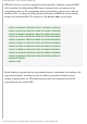


Programming PIC Microcontrollers in BASIC - mikroElektronika
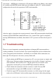
reset circuit — MCLR pin is connected to +5V through a 10K resistor. Below is the scheme
of a rectifier with LM7805 circuit which gives the output of stable +5V, and the minimal
configuration relevant for the operation of a PIC microcontroller.
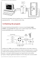
After the supply is brought to the circuit previously shown, PIC microcontroller should look
animated, and the LED diode should blink once every second. If the signal is completely
missing (LED diode does not blink), then check if +5V is present at all the relevant pins of
PIC.
1.7 Troubleshooting
There are several commonly encountered problems of bringing PIC microcontroller to
working conditions. You need to check a few external components and test whether their
values correspond to the desired ones, and finally to see whether all the connections are
done right. We will present a few notes you may find useful.
● Check whether the MCLR pin is connected to +5V, over reset circuit, or simply with
10K resistor. If the pin remains disconnected, its level will be “floating” and it may
work sometimes, but it usually won’t. Chip has power-on-reset circuit, so the
appropriate external pull-up resistor on MCLR pin should be sufficient.
● Check whether the connection with the resonator is stable. For most PIC
microcontrollers to begin with 4MHz resonator is well enough.
● Check the supply. PIC microcontroller consumes very little energy but the supply
needs to be well filtrated. At the rectifier output, the current is direct but pulsating,
http://www.mikroelektronika.co.yu/english/product/books/picbasicbook/01.htm (9 sur 11)05/11/2004 02:10:07