
Specifications


Configuration MC13xx Users Manual Rev. 1.08
6.3.3 Load user profile
Load one of eight user profiles to the PowerUpProfile.
Command: :g<n> <n> = 0 ... 7, c
6.3.4 Load factory profile
The eight factory profiles can be read but not changed by the user.
Command: :f<n> <n> = 0 ... 7
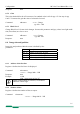
6.4 Video data width, Base/ Full Camera Link®
MC13xx can output video data with 2 x 8-Bit or 2 x 10-Bit via the „Base Camera Link®“ interface, or 8
x 8-Bit or 10 x 8-Bit data via the „Full Camera Link®“ interface. Use register 7 Bits 7/5 to select..
Video data width :r7[7] :r7[5]
2 x 8 0 0
2 x 10 0 1
8 x 8 1 0
10 x 8 1 1
Table 6.4-1
The 10 x 8 - Bit data width lowers the clock speed for a given bandwidth, and needs a compatible frame
grabber. The assignment of the 10 taps to the Camera Link® ports is described in chapter:10*8-Bit As-
signment.
There are no predefined profiles for 10 x 8 Bits stored in the MC1310/11. Any predefined 8 x 8-Bit pro-
file can be used as starting point. Then change :r7 [7,5] to 1 and set Pixel Clock speed as described in:
Frequencies for video data width 10*8 - Bit
. This profile can then be stored as User Profile.
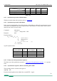
*
MC1302/03 Setting of r7[7] is ignored by the camera.
MC1310/11: After a change of r7[7], change the se-
lected frequency. See: Table selection of clock frequen-
cies.
6.5 Image quality
There are three D/A converter to influence image quality: FPN, Gain, and Black up. FPN, Gain and
especially Black might be adjusted if sensor clock changes. All three parameters are stored in non-
volatile memory as part of the selected profile.
6.5.1 FPN
The Fixed Pattern Noise setting reduces the fixed pattern noise that is typical to CMOS sensors. This
level might be changed if the sensor clock frequency is changed. For adjustment set the lens out of fo-
cus and to a medium grey level. Lower FPN until a heavy pattern appears. Then raise by a few points.
15
Command: :a1<x
1
x
0
>
<x
1
x
0
> : Range, typ. 55h ... 80h