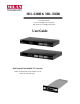
MIL-S2400 & MIL-S1600 Fast Ethernet Switch 16 or 24 10/100 Mbps auto-sensing ports with optional 1 port 100Mbps Fiber Module User Guide With Optional Fiber 100BASE-TX Extension 100Base-FX with Module with SC/ST/MT-RJ/ VF-45 Multi-mode and Single-mode
Regulatory Approval - FCC Class A - UL 1950 - CSA C22.2 No. 950 - EN60950 - CE - EN55022 Class A - EN55024 Canadian EMI Notice This Class A digital apparatus meets all the requirements of the Canadian Interference-Causing Equipment Regulations. Cet appareil numerique de la classe A respecte toutes les exigences du Reglement sur le materiel brouilleur du Canada.
Contents 1. Introduction…….…………….…………….……….………….…… 1 Features …………………………………………..…..…….… 2 Package Contents ………………………..…..……….……… 3 Ethernet Switching Technology ………………….…………… 4 2. Hardware Description ………………..….…..…...………….………… 6 Front Panel ………………………………………...…...………… 6 LED Indicators ……………………………………………………. 7 Real Panel …………………………………………….………….. 8 Desktop Installation ……………………….…….……………….. 9 Rack-mounted Installation …...…………….…………………… 9 3. Optional Fiber Modules ………….…..……….…………….
Introduction Ethernet Switching Technology Ethernet Switching Technology dramatically increases the total bandwidth of a network, eliminates congestion problems inherent with ( CSMA/CD ) protocol, which greatly reduces unnecessary transmissions. Switch Technology has revolutionized networking. First, by allowing two-way, simultaneous transmissions over the same port ( Full-duplex ), which essentially doubled the bandwidth.
Features n Conforms to IEEE 802.3, 802.3u, and 802.
Hardware Description This Section mainly describes the hardware of the MIL-S2400 and MIL-S1600 Switches, and gives a physical and functional overview of each Switch. Front Panel The Front Panel of the MIL-S2400 and MIL-S1600 Switches consists of 16 or 24 10/100Base-TX RJ-45 ports ( Auto MDI/MDIX ) and slot for 100Base-FX Fiber Module. The LED Indicators are also located on the front panel of the Switch. Figure 2-1.
LED Indicators The LED Indicators gives a real-time information of systematic operation status. The following table provides descriptions of LED status and their meaning. Figure 2-2. LED Indicators LED Status Green Off Green Description Power On Off The port is operating at the speed of 100Mbps. 100M Off LK/ACT No device attached or in 10Mbps mode Green The port is active with device(s) attached Blinks The port is receiving or transmitting data. Off Yellow No device attached.
Rear Panel The 3-pronged power plug, On/Off switch, and ventilation fan are located at the rear panel of the MILS2400 and MIL-S1600 Switches as shown in Figure 2-2. The Switch will work in the range 100-240V AC, 50-60Hz. Figure 2-3. The Rear Panel of MIL-S2400 and MIL-S1600 Switches Desktop Installation A. Set the Switch on a sufficiently large flat space with a power outlet nearby. The surface where you put your Switch should be clean, smooth, level and sturdy. B.
Rack-mounted Installation The MIL-S2400 and MIL-S1600 switches includes a rack-mounted kit and can be mount in an EIA standard size, 19-inch Rack, enabling the switch to be placed in a wiring closet with other equipment. Perform the following steps to rack mount the switch: A. Position one bracket to align with the holes on one side of the switch and secure it with the smaller bracket screws. Then attach the remaining bracket to the other side of the switch. Figure 2-4.
Optional Fiber Modules This section introduces the optional 100Base-FX Modules which can be installed on the front panel of the MIL-S2400 and MIL-S1600 Switches. Each optional 100Base-FX Module has a oneport fiber connector. The 100Base-FX Modules are designed to extend the distance between switch and other devices. The maximum distance connected by optical fiber is up to 2 Km ( multi-mode fiber ) or 60 Km ( single-mode fiber ). Figure 3-1.
MIL-S2416ST MIL-S2416MT MIL-S2416VF
LED Indicators of 100base-FX The LED-Indicators provide a real-time information of systematic operation status. The following table provides descriptions of LED Indicators status and their meaning. LED Status Blinks Off Blinks Description This fiber port is transmitting data. No data is be transmitted. This fiber port is receiving data. RX Off Yellow No data is being received. The port is connecting with the device. Link Off FD/COL No device attached.
Installing 100Base-FX Module The optional 100Base-FX Modules are designed to be inserted in the extension slot. Before installation, ensure that the power is disconnected. The module is NOT hot-swappable. Follow the steps below to install the optional 100Base-FX Module: 1. Power the MIL-S2400 and MIL-S1600 Switches OFF before installing the 100Base-FX Module. 2. Unscrew the thumbscrews on the blank bracket. Remove the blank bracket and set aside, but do not discard it.
Troubleshooting This section is intended to help you solve the most common problems on the MIL-S2400 and MILS1600 Switches. n Faulty or loose cables Look for loose or obviously faulty connections. If they appear to be OK, make sure the connections are snug. IF that does not correct the problem, try a different cable. n Non-standard cables Non-standard and miswired cables may cause numerous network collisions and other network problem, and can seriously impair network performance.
Technical Specification This section provides the specifications for the MIL-S2400 and MIL-S1600 Switches. Specifications Standard IEEE 802.3 10Base-T Ethernet, IEEE 802.
P/N: 90000372_A