MIL-S24000T 24-Port 1000BASE-T Gigabit Ethernet Switch USER GUIDE
Regulatory Approval - FCC Class A - UL 1950 - CSA C22.2 No. 950 - EN60950 - CE - EN55022 Class A - EN55024 Canadian EMI Notice This Class A digital apparatus meets all the requirements of the Canadian Interference-Causing Equipment Regulations. Cet appareil numerique de la classe A respecte toutes les exigences du Reglement sur le materiel brouilleur du Canada.
Table of Contents 1. Introduction Gigabit Ethernet Technology Switching Technology Features Package Contents 2. Hardware Description Front Panel Rear Panel LED Indicators 3. Hardware Installation Desktop Installation Rack mounted Installation Power On 4.
1. Introduction Gigabit Ethernet Technology Gigabit Ethernet is an extension of IEEE 802.3 Ethernet utilizing the same packet structure, format, and support for CSMA/CD protocol, full duplex, flow control, and management objects, but with a tenfold increase in theoretical throughput over 100-Mbps Fast Ethernet and a hundredfold increase over 10-Mbps Ethernet.
to users on a local area network. A switch increases capacity and decreases network loading by making it possible for a local area network to be divided into different segments which do not compete with each other for network transmission capacity, giving a decreased load on each. The switch acts as a high-speed selective bridge between the individual segments. The switch automatically forwards traffic that needs to go from one segment to another, without interfering with any other segments.
Package Contents Unpack the contents of the package and verify them against the checklist below. MIL-S24000T Gigabit Ethernet Switch AC Power Cord Rack Mount Ears Four Adhesive Rubber Feet User's Guide Warranty Card If any item is missing or damaged, please contact your local dealer for service.
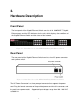
2. Hardware Description Front Panel The front panel of the Gigabit Ethernet Switch consists of 24 1000BASE-T Gigabit Ethernet ports and the LED Indicators for the unit, which displays the conditions of the Gigabit Ethernet Switch and the status of the network. Figure 2-1. Front Panel view of the MIL-S24000T Gigabit Ethernet Switch Rear Panel The rear panel of the Gigabit Ethernet Switch consists of an AC power connecter and a power switch. Figure 2-2.
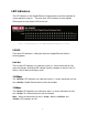
LED Indicators The LED indicators of the Gigabit Ethernet Switch provide a real-time indication of system operating statuses. There are three LED-indicators for each Gigabit Ethernet port and one Power LED for the Unit. Figure 2-3. LED Indicators on the MIL-S24000T Gigabit Ethernet Switch POWER The Power LED indicator is solid green when the Gigabit Ethernet Switch is receiving power. Link/Act The Link/Act LED indicators are solid when there is a secure connection (or link) to the desired port.
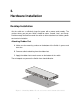
3. Hardware Installation Desktop Installation Set the switch on a sufficiently large flat space with a power outlet nearby. The surface where you put your switch should be clean, smooth, level, and sturdy. Provide enough clearance around the switch to allow attachment of cables, power cord and air circulation. Attaching Rubber Feet A. Make sure the mounting surface on the bottom of the Switch is grease and dust free. B. Remove adhesive backing from the rubber feet. C.
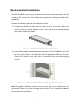
Rack-mounted Installation The MIL-S24000T comes with a rack-mounted kit and can be mounted in an EIA standard size, 19-inch rack. The Switch can be placed in a wiring closet with other equipment. Perform the following steps to rack mount the switch: A. Position one bracket to align with the holes on one side of the switch and secure it with the smaller bracket screws. Then attach the remaining bracket to the other side of the Switch. Figure 3-2. Attach mounting brackets with screws B.
Power On Connect the power cord to the power socket on the rear panel of the Switch. Connect the other end of the cord to an appropriate power outlet. Press the power On/Off switch to the on position and check the power indicator on the front panel to see if power is properly supplied.
4. Technical Specifications General Specifications Standards: Protocol: Data Transfer Rate: Topology: Network Cables: Number of Ports: IEEE 802.3ab 1000BASE-T IEEE 802.3u 100BASE-TX IEEE 802.3 10BASE-T IEEE 802.3x Flow Control CSMA/CD Ethernet: 10Mbps (Half-duplex) 20Mbps (Full-duplex) Fast Ethernet: 100Mbps (Half-duplex) 200Mbps (Full-duplex) Gigabit Ethernet: 2000Mbps (Full-duplex) Star Ethernet: 2-pair UTP Cat. 3,4,5, Unshielded Twisted Pair (UTP )Cable Fast Ethernet: 2-pair UTP Cat.
Performance Specifications Transmission Method: RAM Buffer: Filtering Address Table: MAC Address Learning: Store-and-forward 400K Bytes per device 8K MAC address per device Self-learning, auto-aging 10
Appendix A: Regulatory Information FCC Warning This equipment has been tested and found to comply with the regulations for a Class A digital device, pursuant to Part 15 of the FCC Rules. These limits are designed to provide reasonable protection against harmful interference when the equipment is operated in a commercial environment.
condition is not achieved due to uneven mechanical loading. d) Circuit Overloading- Consideration should be given to the connection of the equipment to the supply circuit and the effect that overloading of circuits might have on over current protection and supply wiring. Appropriate consideration of equipment nameplate ratings should be used when addressing this concern. e) Reliable Earthing-Reliable earthing of rack-mounted equipment should be maintained.
90000423 Rev A 13