MIL-S5000T 5-Port 1000BASE-T Gigabit Ethernet Switch USER GUIDE
Regulatory Approval - FCC Class A - UL 1950 - CSA C22.2 No. 950 - EN60950 - CE - EN55022 Class A - EN55024 Canadian EMI Notice This Class A digital apparatus meets all the requirements of the Canadian Interference-Causing Equipment Regulations. Cet appareil numerique de la classe A respecte toutes les exigences du Reglement sur le materiel brouilleur du Canada.
Table of Contents 1. Introduction Gigabit Ethernet Technology Switching Technology Features Package Contents 2. Hardware Description Front Panel Rear Panel LED Indicators 3. Hardware Installation Desktop Installation Power On 4.
1. Introduction Gigabit Ethernet Technology Gigabit Ethernet is an extension of IEEE 802.3 Ethernet utilizing the same packet structure, format, and support for CSMA/CD protocol, full duplex, flow control, and management objects, but with a tenfold increase in theoretical throughput over 100-Mbps Fast Ethernet and a hundredfold increase over 10-Mbps Ethernet.
to users on a local area network. A switch increases capacity and decreases network loading by making it possible for a local area network to be divided into different segments which do not compete with each other for network transmission capacity, giving a decreased load on each. The switch acts as a high-speed selective bridge between the individual segments. The switch automatically forwards traffic that needs to go from one segment to another, without interfering with any other segments.
Package Contents Unpack the contents of the package and verify them against the checklist below. MIL-S5000T Gigabit Ethernet Switch External Power Adapter Four Adhesive Rubber Feet User's Guide Warranty Card If any item is missing or damaged, please contact your local dealer for service.
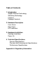
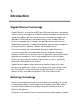
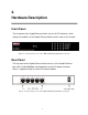
2. Hardware Description Front Panel The front panel of the Gigabit Ethernet Switch consists of LED Indicators, which display the conditions of the Gigabit Ethernet Switch and the status of the network. Figure 2-1. Front Panel view of the MIL-S5000T Gigabit Ethernet Switch Rear Panel The rear panel of the Gigabit Ethernet Switch consists of five Gigabit Ethernet ports with 10/100/1000Mbps Auto-Negotiation and the DC power connecter. Power is supplied through an external AC power adapter. Figure 2-2.
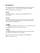
LED Indicators The LED indicators of the Gigabit Ethernet Switch provide a real-time indication of system operating statuses. There are three LED-indicators for each Gigabit Ethernet port and one Power LED for the Unit. POWER The Power LED indicator is solid green when the Gigabit Ethernet Switch is receiving power. Link/Act The Link/Act LED indicators are solid when there is a secure connection (or link) to the desired port. A blinking LED indicator signifies reception or transmission (i.e.
3. Hardware Installation Desktop Installation Install the MIL-S5000T Gigabit Ethernet Switch in a location that conforms to the acceptable operation temperature and humidity ranges (see Technical Specifications). It is recommended that the site be free from strong electromagnetic source, vibration, dust, and direct sunlight. A minimum of 10cm of space on the left and right hand side of the Switch is required for ventilation purposes.
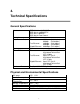
4. Technical Specifications General Specifications Standards: Protocol: Data Transfer Rate: Topology: Network Cables: Number of Ports: IEEE 802.3ab 1000BASE-T IEEE 802.3u 100BASE-TX IEEE 802.3 10BASE-T IEEE 802.3x Flow Control CSMA/CD Ethernet: 10Mbps (Half-duplex) 20Mbps (Full-duplex) Fast Ethernet: 100Mbps (Half-duplex) 200Mbps (Full-duplex) Gigabit Ethernet: 2000Mbps (Full-duplex) Star Ethernet: 2-pair UTP Cat. 3,4,5, Unshielded Twisted Pair (UTP )Cable Fast Ethernet: 2-pair UTP Cat.
Performance Specifications Transmission Method: RAM Buffer: Filtering Address Table: Packet Filtering/Forwarding Rate: MAC Address Learning: Store-and-forward 256K Bytes per device 8K MAC address per device Full wire speed Self-learning, auto-aging 8
Appendix A: Regulatory Information FCC Warning This equipment has been tested and found to comply with the regulations for a Class A digital device, pursuant to Part 15 of the FCC Rules. These limits are designed to provide reasonable protection against harmful interference when the equipment is operated in a commercial environment.
90000424 Rev A 10