ShAir Office Multi-Function Internet & Wireless Gateway Models MIL-W0311 & MIL-W1311 Broadband Internet Access Wireless Access Point Dial-in RAS Print Server User’s Guide
TABLE OF CONTENTS CHAPTER 1 INTRODUCTION.............................................................................................. 1 Wireless Gateway Features .............................................................................................. 1 Package Contents .............................................................................................................. 4 Physical Details .........................................................................................................
URL Filter ........................................................................................................................ 66 Virtual Servers................................................................................................................. 68 DMZ.................................................................................................................................. 73 CHAPTER 10 ACCESS CONTROL...................................................................................
1 Chapter 1 Introduction This Chapter provides an overview of the Wireless Gateway's features and capabilities. Congratulations on the purchase of your new Wireless Gateway Multi-Function Wireless Gateway.
Wireless Gateway User Guide • Multi Segment LAN Support. LANs containing one or more segments are supported, via the Wireless Gateway's built-in static routing table. If NAT (Network Address Translation) is disabled, the Wireless Gateway will function as a static router. Internet Access Features • Shared Internet Access. All users on the LAN or WLAN can access the Internet through the Wireless Gateway, using only a single external IP Address.
Introduction Advanced Internet Functions • • Virtual Servers. This feature allows Internet users to access Internet servers on your LAN. The required setup is quick and easy. User-Defined Virtual Servers. Internet users can access non-standard Internet Servers on your LAN by using this feature. • Special Internet Applications. Internet applications such as Internet Videoconferenc- • DMZ. One (1) PC on your local LAN can be configured to allow unrestricted 2-way • URL Filter.
Wireless Gateway User Guide NAT Firewall Protection The firewall protection provided by the Wireless Gateway is an intrinsic side effect of NAT (Network Address Translation). All users on the LAN share a single external IP address. From the external viewpoint, there is no network, only a single device. For internal users, the Wireless Gateway acts as a “transparent proxy server”, translating the multiple internal IP addresses into a single external IP address.
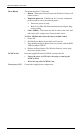
Introduction Wireless On - Wireless connection available; Wireless Access Point is ready for use. Off - No Wireless connection available. Flashing - Data is transmitted or received via the Wireless access point. This includes "network traffic" as well as user data. Print Error On - Printer error detected. Off - No printer error detected. Print Act On - Connection to printer established. Off - No connection to printer; printer is Off or Off-line. Flashing - Data is being transmitted to the printer.
Wireless Gateway User Guide Reset Button This button has three (3) functions: • Reboot. When pressed and released, the Wireless Gateway will reboot (restart). • Diagnostic print-out. If held down for 3 seconds, a diagnostic print-out will be sent to the attached printer. • • Ensure the printer is ready. • Both Print LEDs will flash simultaneously during the diagnostic printing. Clear All Data. This button can also be used to clear ALL data and restore ALL settings to the factory default values.
Introduction DIP Switches DIP Switch Setting Description 1=off 2=off Normal Operation. 1=off 2=on DHCP Server function disabled. 1=on 2=off Used to restore Default IP Address and clear Password (See below). 1=on 2=on Normal Operation. Restore Default IP Address and Clear Password If the Wireless Gateway's IP Address or password is lost, the following procedure can be used to recover from this situation. 1. Turn the power to the Wireless Gateway OFF. 2. Set DIP switch 1 ON. 3.
2 Chapter 2 Installation This Chapter covers the physical installation of the Wireless Gateway. Requirements • Ethernet LAN (10/100BaseT) and the TCP/IP protocol. • For Internet Access, an Internet Access account with an ISP, and either of: • A DSL or Cable modem (for WAN port usage) • An analog modem or ISDN TA (for serial port usage) • To use the Wireless Access Point, all Wireless devices must be compliant with the IEEE802.11b specifications.
Installation 2. Insert Wireless PCMCIA card Ensuring the supplied Wireless PCMCIA card is the right way up, insert it into the slot on the rear. Push it firmly until it clicks into position. 3. Connect LAN Cable Connect a standard LAN cable from a 10BaseT or 100BaseT Hub on your LAN to the “HUB” port on the Wireless Gateway. 4. Connect WAN Cable If you have a DSL modem or Cable modem, connect it to the WAN port on the Wireless Gateway. Use the cable supplied with your modem.
3 Chapter 3 Configuration This Chapter provides details of the configuration process. Overview This chapter describes the procedure for: • Quick setup • Wireless access point configuration • Using the Status screens PCs on your local LAN may also require configuration. For details, see Chapter 4 - PC Configuration. Other configuration may also be required, depending on which features and functions of the Wireless Gateway you wish to use.
Configuration Where use of a certain feature requires that PCs or other LAN devices be configured, this is also explained in the relevant chapter. Configuration Program The Wireless Gateway contains an HTTP server. This enables you to connect to it, and configure it, using your Web Browser. Most Browsers should work, provided they support HTML tables and forms.
Wireless Gateway User Guide Password If you have assigned a password to the Wireless Gateway (on the Options screen) you will be prompted for the password, as shown below. (If no password has been set, this dialog will not appear.) Figure 4: Password Dialog • Leave the "User Name" blank. • Enter the password for the Wireless Gateway, as set on the Options screen. Navigation & Data Input • Use the menu bar on the left of the screen, and the "Back" button on your Browser, for navigation.
Configuration Quick Setup Screen The Quick Setup screen, like the example below, will be displayed when you first connect. Figure 5: Quick Setup Screen Quick Setup - Overview This screen contains all the basic data to make the Wireless Gateway operational. For many users, the default values will be satisfactory, and no changes will be required. • Router Most users do not need to change these values.
Wireless Gateway User Guide • Wireless Access Point To use the Wireless Access Point: • All Wireless devices must have the same SSID. Either the Wireless Access Point or the Wireless clients can be changed to ensure this. • All Wireless devices must have the same settings for WEP (Wired Equivalent Privacy). By default, WEP on the Wireless Gateway is Disabled, so clients also need to have WEP Disabled.
Configuration WAN Enable Ethernet Port IP Address from ISP Normally, this should be left at the default value of Enabled. • If no DSL or Cable modem is connected to the WAN (Ethernet) port, then this setting should be Disabled. • If Internet access via the Serial Port is Enabled, this setting will be automatically Disabled. It is not possible to simultaneously use both the WAN (Ethernet) port and the Serial (RS232) port for Internet access. Dynamic IP Address.
Wireless Gateway User Guide WEP Status This will state "Enabled" or "Disabled". The default is "Disabled". • In order to use the Wireless Gateway's access point, the client wireless stations must have the same settings for WEP. • To change the Wireless Gateway's WEP settings, use the Wireless screen, described in the following section. Buttons Save Save any data you have entered on this screen. Remember to save before changing to another screen.
Configuration Wireless Screen The Wireless Access Point settings must match the other Wireless stations. To change the Wireless Gateway's default settings for the Wireless Access Point, use the Wireless link on the main menu to reach the Wireless screen. An example screen is shown below. Figure 6: Wireless Screen Data – Wireless Screen Configuration Regulatory Domain It is illegal to use this device in any location outside of the regulatory domain.
Wireless Gateway User Guide SSID (ESSID) To communicate, all Wireless stations MUST use the same SSID/ESSID. The default value is default Note! The SSID is case sensitive. Channel No. Select the value you wish to use on your Wireless LAN. If you experience lost connections and/or slow data transfers you may need to experiment with different channels to see which is the best. WEP Data Privacy Off If OFF (default), data is NOT encrypted before being transmitted.
Configuration Existing Stations New station Address • This lists the Wireless stations you have entered. If you have not entered any stations, this list will be empty. • To delete an entry, select it, and click the "Delete" button. Multiple entries may be selected by hold down the CTRL key while selecting. (On the Macintosh, use SHIFT instead of CTRL.) • Use this field to add a new station to the list. Just enter its address here, and click the "Add" button.
Wireless Gateway User Guide Status Screen Use the Status link on the main menu to view this screen. The LAN Status link on the menu will result in a screen like the example below. Figure 7: Status Screen Data - Status Screen LAN Device Name This shows the name of the device. IP Address The IP Address of this device, as seen by other devices on the Internal LAN. Network Mask The Network Mask (Subnet Mask) for the IP Address above.
Configuration DHCP Table Use this link to view the IP Addresses which have been allocated to LAN devices, or the Dial-in user, by the DHCP Server function. The DHCP Table contains the following data: • Port - The port which the DHCP client used to access this device. Possible values are LAN, WLAN (Wireless LAN), and RS232 (serial port). • IP Address - The IP Address which has been allocated by the DHCP server to the DHCP client.
Wireless Gateway User Guide Access Control Log This log shows connection requests which have been blocked by the Access Control feature or the built-in NAT Firewall. Accesses which have been blocked for other reasons (e.g. URL filter, incorrect dial-in password, incorrect WEP settings on the WLAN) are NOT shown in this log. (The "Internet Access Log" can be used to view connection attempts which have been blocked by the URL filter.
Configuration WAN Status – Direct Connection If the WAN (Ethernet) port is using PPPoE, then clicking the WAN Status link on the Status screen will reveal a screen like the following. Figure 8: WAN Status – Direct Connection Data WAN Status Physical Address The "Hardware" address of this device, as seen by other devices on the WAN. IP Address The IP Address of this device, as seen by devices on the WAN. (This device has 2 IP Addresses; one for the local LAN, and another for the WAN port.
Wireless Gateway User Guide WAN Status – PPPoE If the WAN (Ethernet) port is using PPPoE, then clicking the WAN Status link on the Status screen will reveal a screen like the following. Figure 9: WAN Status – PPPoE Status Data WAN Status Physical Address The "Hardware" address of this device, as seen by other devices on the WAN. IP Address The IP Address of this device, as seen by devices on the WAN. (This device has 2 IP Addresses; one for the local LAN, and another for the WAN port.
Configuration Buttons Connect Disconnect N/A If not connected, this button will display "Connect" and can be used to establish a connection to your ISP If connected to your ISP, this button will display "Disconnect" and can be used to hang up the connection. If PPPoE is not configured, this button will display "N/A" (not applicable). Clear Log Delete all data currently in the Log. This will make it easier to read new messages. Refresh Contact this device and update the Log data.
Chapter 4 PC Configuration 4 This Chapter details the PC Configuration required on the local ("Internal") LAN. Overview For each PC, the following may to be configured: • TCP/IP network settings • Internet Access configuration • Network printer • Wireless configuration Windows Clients This section describes how to configure Windows clients for: • Internet access via the Wireless Gateway • Printing using the printer attached to the Wireless Gateway.
PC Configuration Figure 10: Network Configuration 2. 3. Select the TCP/IP protocol for your network card. Click on the Properties button. You should then see a screen like the following. Figure 11: IP Address (Win 95) Ensure your TCP/IP settings are correct, as follows: Using DHCP To use DHCP, select the radio button Obtain an IP Address automatically. This is the default Windows settings. Restart your PC to ensure it obtains an IP Address from the Wireless Gateway.
Wireless Gateway User Guide Figure 12: Gateway Tab (Win 95/98) • On the DNS Configuration tab, ensure Enable DNS is selected. If the DNS Server Search Order list is empty, enter the DNS address provided by your ISP in the fields beside the Add button, then click Add. Figure 13: DNS Tab (Win 95/98) If your LAN has a Router, the LAN Administrator must re-configure the Router itself. Refer to Chapter 8 - Routing for details.
PC Configuration Internet Access If you are using the Wireless Gateway for Internet access: • Ensure that the DSL modem, Cable modem, or other permanent connection is functional. • Use the following procedure to configure your Browser to access the Internet via the LAN, rather than by a Dial-up connection. 1. 2. 3. Select Start Menu - Settings - Control Panel - Internet Options. Select the Connection tab, and click the Setup button.
Wireless Gateway User Guide Printing Setup The Wireless Gateway provides printing support for 2 methods of printing from Windows: • Print Port Driver. After installing the Print Port Driver, Windows users can print directly to the Wireless Gateway. Print jobs are spooled (queued) on each PC. The supplied Print Port Driver supports Windows 95/98, Windows ME, Windows NT4.0, and Windows 2000. • LPD/LPR Printing. If using Windows NT 4.0 Server or Windows 2000 Server, LPD/LPR printing can be used.
PC Configuration If you see the following error message, either install Internet Explorer 4 or later, or follow the procedure in the "Trouble Shooting - Printing" section of Appendix A. 7. 8. A pop-up message will inform you if the port has been created successfully, and then the Windows Add Printer wizard will start. • Select the correct Printer Manufacturer and Model, or use the "Have Disk" option if appropriate. • If desired, change the Printer name so it indicates the device used (e.g.
Wireless Gateway User Guide Figure 15: Print Port Configuration Items shown on this screen are as follows: Port If desired, click Browse to select a different device. (The Select Device Port button is provided to allow this software to work with multi-port models.) The Port Name is shown in the Printer's Properties. Banner Retry Interval Check this option to print a banner page before each print job. • If using a PostScript Printer, check the PostScript box.
PC Configuration 8. 9. In the Shared dialog box, enter the shared printer name. The shared name is how other users will see this printer. You should advise client PCs of the Server name and this printer name. Click OK to save and exit. Windows 2000 Server Configuration The LPD/LPR Port is not enabled by default. To enable it, use this procedure: 1. In Control Panel, select Add/Remove Programs, then Windows Components. 2. Select Other Network File and Print Services, then click the Details button.
Wireless Gateway User Guide Figure 17: Windows 2000: Select Port 4. 5. 6. 7. 8. In the Dialog requesting Name of Address of server providing lpd, enter the IP address of the Wireless Gateway. For Name of printer or print queue on that server, enter L1. Click OK, and then Next, and continue the Wizard. At the Select Sharing screen, select the Radio Button for Share As, and enter the shared printer name. The shared name is how other users will see this printer.
PC Configuration Dial-in Configuration This section describes how to configure your PC to use the Wireless Gateway's RAS Dial-in feature. To use the RAS Dial-in feature of the Wireless Gateway: • An Analog Modem or ISDN TA must be connected to the Serial Port on the Wireless Gateway. • The Wireless Gateway's Serial Port screen must be configured for Dial-in access, and Dial-in Users must be created. See Chapter 6 - Serial Port for details.
Wireless Gateway User Guide Dial-up Networking Properties Log on to network This setting refers to a logon to a Server on your LAN, not the login to the Wireless Gateway. This should be disabled; checking this option will cause a minor delay in establishing a connection. Enable software compression Normally, this should be checked, but the Wireless Gateway will function with either Checked or Unchecked.
PC Configuration Macintosh Clients Internet Access From your Macintosh, you can access the Internet via the Wireless Gateway. The procedure is as follows. 1. 2. 3. 4. Open the TCP/IP Control Panel. Select Ethernet from the Connect via pop-up menu. Select Using DHCP Server from the Configure pop-up menu. The DHCP Client ID field can be left blank. Close the TCP/IP panel, saving your settings.
Wireless Gateway User Guide Linux Clients Internet Access on Linux Ensure you are logged in as "root" before attempting any changes. By default, most Unix installations use a fixed IP Address. If you wish to continue using a fixed IP Address, make the following changes to your configuration. • Set your "Default Gateway" to the IP Address of the Wireless Gateway. • Ensure your DNS (Nameserver) settings are correct.
PC Configuration Other Unix Systems For Internet Access via the Wireless Gateway • Ensure the "Gateway" field for your network card is set to the IP Address of the Wireless Gateway. • Ensure your DNS settings are correct. LPD Printing To use LPD printing to the Wireless Gateway's printer, install an LPD printer using the standard procedure for your system. • Use the Wireless Gateway's IP Address as the location of the remote host • Use L1, L2, or L3 for the name of the printer on the remote host.
5 Chapter 5 DHCP This Chapter covers the use of DHCP, using either an existing DHCP Server or the Wireless Gateway's DHCP Server function. Overview If your LAN does not use DHCP, and you do not wish to use DHCP, you can ignore this chapter. What DHCP Does A DHCP (Dynamic Host Configuration Protocol) server allocates a valid IP address to a DHCP client (PC or device) upon request. • The client request is made when the client device boots.
DHCP To Configure your PCs to use DHCP This is the default setting for TCP/IP under Windows 95/98/ME. See Chapter 4 – Client Configuration for the procedure to check these settings.
6 Chapter 6 Serial Port This Chapter details using the Serial (RS232) Port, either for Internet Access or Dial-in use. Overview The Serial (RS232) port can be used for Internet Access or to provide RAS (Dial-in) access to your LAN. • If used for Internet access, the WAN (Ethernet) Port cannot be used. • Both Internet Access and Dial-in Access can be enabled simultaneously, but if the modem is in use, a Dial-in user will only get a "busy" signal on their telephone line.
Serial Port Data - Serial Port Screen Modem Type Select None if nothing is connected to the Serial Port, or you do not wish use to use the Serial Port. For Permanent Connection (leased line): • Ensure the Serial Line Speed is set to match the speed on your leased line. • Ignore the Telephone numbers and "Disconnect after Idle" setting. For Modem: • If your modem is in the drop-down list, just select it. • If your modem is not in the list, select "_Standard Modem" and test to see if this works.
Wireless Gateway User Guide IP Address from ISP DNS IP Address Select the appropriate option: • Dynamic This is the default, and the most common. Leave this selected if your ISP allocates an IP Address to the Wireless Gateway upon connection. • Fixed IP Address Select this if your ISP has allocated you a fixed IP Address, then enter the IP Address in the fields provided. The DNS (Domain Name Server) translates names (e.g. microsoft.com) to IP Addresses.
Serial Port Status Use this link to view the Serial Port status screen, described later in this chapter. Modem Properties Screen This screen will be displayed when the "Modem Properties" button on the Serial Port screen is clicked. Normally, it is not necessary to access this screen. Figure 20: Modem Properties Screen Data – Modem Properties Screen Initial String Initial String This is a series of AT commands used to correctly configure your modem or ISDN.
Wireless Gateway User Guide Buttons Save Save the data on this screen. Note that if the current modem was not "Other" type, and you changed the Initial String, you can NOT use "Save". You must use "Save as Other" instead. Save as "Other" Assign the data shown on screen to the "Other" modem type, regardless of the modem selected on the Serial Port screen. You should then select "Other" as the Modem to use. Cancel Reverse any changes since the last "Save" operation.
Serial Port Dial -in Users This section describes how to create and manage remote users who wish to use the Wireless Gateway's RAS Dial-in facility. For details of configuring the remote PC to use Dial-in access, refer to Dial-in in Chapter 4 Client PC Configuration. Overview Upon connection, the Wireless Gateway will allocate an IP Address to the Dial-in user. To other LAN users and devices, the Dial-in user will be valid device on the LAN.
Wireless Gateway User Guide Dial-in Users Screen This screen is reached via the Dial-in Users link on the Serial Port screen. Figure 21: Dial-in Users Screen Data – Dial-in Users Screen Existing Users Dial-in Access Other Users • This lists all users who have Dial-in permission. • If no users have dial-in permission, this list will be empty. • Select the user or users you wish to change. Multiple users can be selected by holding down the CTRL key while selecting.
Serial Port Buttons >> Use the " >> " button to remove Dial-in access for any users selected in the "Dial-in Users" list. << Use the " << " button to allow Dial-in access for any users selected in the "Other Users" list. Del Delete the selected user or users in the list above the button. Edit Modify the selected user in the list above the button. Only 1 user should be selected. Create This will add a new user to the database.
Wireless Gateway User Guide Dial-in Enable dial-in access Use this to suspend or enable dial-in access. This setting can also be changed on the Dial-in Users screen. Enforce connection time limit If checked, the Wireless Gateway will terminate the Dial-in connection after the specified period. The time period can be set from 1 to 999 minutes. If unchecked, the connection time-out set on the Serial Port screen will be used.
Serial Port Serial Port Status This screen is reached by either of the following: • Status Screen - Serial Port Status link • Serial Port Screen - Status link. An example screen is shown below. Figure 23: Serial Port Status Screen Overview • Status - This section displays the current connection status for the serial port connection. • Log - Displays log messages relating to the connection status.
Wireless Gateway User Guide Physical Link If operating, the link will show ON. This means the modem was able to connect to the number dialed. PPP Link If ON, a PPP connection was successfully negotiated. PPP IP Address This has 2 possible meanings, depending of the type of connection: User • Internet Access - This is the IP Address used by this device, as seen by Internet users. This address is provided by your ISP. • Dial-in - This is the IP Address used by the remote user.
Serial Port Start PPP Having established a physical connection, a PPP connection is now being established. PPP up fail The PPP connection could not be established. PPP up successfully The PPP connection was established successfully. Stop PPP The PPP connection was terminated. This will occur at the end of a session, or an error condition. Try to hang up Attempting to get the modem to hang up. Time out There was no response from the modem No carrier No answer The number dialed did not answer.
7 Chapter 7 Options This Chapter details the options available on the Wireless Gateway's "Options" screen. Overview An example Options screen is shown below. Figure 24: Options Screen Password Once a password is entered, it is required in order to change the device configuration. Passwords are case sensitive and can be up to 8 alphanumeric characters (no spaces or punctuation). To create or change the password, enter the required password in both the New Password and Verify Password input fields.
Options DNS (Domain Name Server • These entries are optional. The main DNS (Domain Name Server) is either provided by your ISP, or entered on the Quick Setup screen. • If desired, enter any other DNS IP Addresses here. The first available DNS will be used. NAT (Network Address Translation) NAT allows PCs on your LAN to share a single external (Internet) IP Address. This IP Address is supplied by your ISP. Use the following to determine whether or nor you need NAT.
Wireless Gateway User Guide 2. In the "Address" bar, enter "HTTP://" followed by the WAN IP Address of the Wireless Gateway. If the port number is not 80, the port number is also required. (After the IP Address, enter ":" followed by the port number.) e.g. HTTP://123.123.123.123:8080 This example assumes the WAN IP Address is 123.123.123.123, and the port number is 8080. Routing Table This link provides access to a standard static routing table.
Options Printer Object Type Sets the type of printer attached. The default setting is "LaserWriter". If the attached printer is not a LaserWriter (or compatible), then you must: • Install the correct printer driver for the printer on each Apple system requiring printer access • Check your Printer's user manual or manufacturer's Web site and find the correct "Printer Object Type" • Enter the correct "Printer Object Type" on this screen.
Chapter 8 Routing 8 This Chapter explains the Routing features of the Wireless Gateway. Overview • If you don't have other Routers or Gateways on your LAN, ignore the "Routing" page completely. • If the Wireless Gateway is only acting as a Gateway for the local LAN segment, ignore the "Routing" page even if your LAN has other Routers. • If your LAN has a standard Router (e.g.
Routing Figure 26: Routing Screen Data - Routing Screen RIP Enable RIP Check this to enable the RIP (Routing Information Protocol) feature of the Wireless Gateway. The Wireless Gateway supports RIP 1 only. Static Routing Table Select Entry This drop-down list shows all entries in the Routing Table. • To view or change an entry, select it, then click the Get Data button. • After making any required changes, click the Update button to save your changes.
Wireless Gateway User Guide Delete Delete the entry selected in the drop-down list, regardless of whether its details are shown on screen. Update Update the entry selected in the drop-down list, using the data shown on screen. List All List all entries in the Routing table. Save Save the RIP setting. This has no effect on the Static Routing Table. Cancel Reverse any changes made since the last "submit" operation (i.e. since clicking any other button).
Routing Static Routing - Example Figure 27: Routing Example For the Wireless Gateway's Routing Table For the LAN shown above, with 2 routers and 3 LAN segments, the Wireless Gateway requires 2 entries as follows. Entry 1 (Segment 1) Destination IP Address 192.168.1.0 Network Mask 255.255.255.0 (Standard Class C) Gateway IP Address 192.168.0.100 (Wireless Gateway's local Router) Interface LAN Metric 1 Entry 2 (Segment 2) Destination IP Address 192.168.2.0 Network Mask 255.255.255.
Chapter 9 Advanced Internet 9 This Chapter explains how to use the Wireless Gateway's "Advanced Internet" features. Overview For situations where the Wireless Gateway is being used to provide shared Internet access, the following advanced features are provided. • Special Internet Applications • URL Filter • Virtual Servers • DMZ This chapter contains details of the configuration and use of each of these features.
Advanced Internet Special Internet Applications This feature is only required if you wish to use Internet applications which require 2-way communication, multiple connections, or combined TCP/UDP connections. Examples of such applications are Internet Videoconferencing, Telephony, Games Servers, and other special-purpose Servers. Generally, you will become aware of the need for this feature when an Internet application is unable to function correctly.
Wireless Gateway User Guide Managing Special Application Entries Enable 1. 2. 3. 4. Select the entry from the drop-down list Click "Get Data" Check the Enable checkbox Click "Update" Disable As above, but uncheck the Enable checkbox. Disable all On the Advanced Internet screen, you can Enable or Disable the Special Applications feature. Delete 1. 2. Select the entry from the drop-down list Click "Delete" Modify (Edit) 1. 2. 3. 4.
Advanced Internet Incoming Protocol The protocol (TCP or UDP) used when the application or service sends data to you. Port Range: Start The start of the range of port numbers used by the application server when data is sent to you. If using only one port number, enter it in both the "Start" and "Finish" fields. Port Range: Finish The end of the range of port numbers used by the application server, when data is sent to you. Buttons Clear Form Clears all data, ready for input of a new entry.
Wireless Gateway User Guide URL Filter The URL Filter provides a means to block access to undesirable Web sites. The blocking action applies to all PCs accessing the Internet via the Wireless Gateway. Operation The URL Filter feature works by matching the "Filter Strings" (text strings) against the requested URL. For example, by inputting the word “bad” in the URL Filter, any URL containing the letters “bad” in it will be blocked.
Advanced Internet URL Filter Screen Figure 30: URL Filter Screen Data - URL Filter Screen Site List Site List This lists any existing entries. If you have not entered any values, this list will be empty. Filter String To add an entry to the list, enter it here, and click the "Add" button. An entry may be a Domain name (e.g. www.trash.com) or simply a string (e.g. ads/ ) Any URL which contains ANY entry ANYWHERE in the URL will be blocked.
Wireless Gateway User Guide Virtual Servers This feature allows you to make Servers on your LAN accessible to Internet users. Normally, Internet users would not be able to access a server on your LAN because: • Your Server does not have a valid external IP Address. • Attempts to connect to devices on your LAN are blocked by the firewall in this device. The "Virtual Server" feature solves these problems and allows Internet users to connect to your servers, as illustrated below.
Advanced Internet Virtual Server Screen The Virtual Servers screen is reached by the Advanced Internet - Virtual Servers link. Figure 32: Virtual Server Screen. Data – Virtual Server Screen WAN IP Address Current IP Address This shows the IP Address which Internet users must use to connect to any of your Virtual Servers. • To Internet Users, ALL of your Virtual Servers have the same IP Address. • This IP Address is allocated by your ISP. It is better to have a fixed IP Address.
Wireless Gateway User Guide LAN IP Address • Enter the IP Address of a PC on your LAN. • You must install and configure the appropriate Server software on the PC entered here. • If using DHCP, the LAN IP Address of a PC may change. To solve this problem, use either of these methods: • Assign a fixed IP Address to the Server PC, ensuring that its IP Address is NOT within the address range allocated by the DHCP Server.
Advanced Internet Managing User Defined Virtual Servers Enable a Server 1. 2. 3. 4. Select the required entry from the drop-down list Click "Get Data" Check the Enable checkbox Click "Update" Disable a Server As above, but uncheck the Enable checkbox. Disable all Servers On the Advanced Internet screen, you can Enable or Disable the Virtual Servers feature. Delete 1. 2. Select the entry from the drop-down list Click "Delete" Modify (Edit) 1. 2. 3. 4.
Wireless Gateway User Guide Internal Port Number Enter the port number used by the Server to connect to clients. External Port Number The port number used by clients when connecting to the Server. This is normally the same as the Internal Port Number. If it is different, this device will perform a "mapping" or "translation" function, allowing the server to use one port address, while clients use a different port address. Buttons Clear Form Clears all data, ready for input of a new entry.
Advanced Internet DMZ This feature, if enabled, allows one (1) computer on your LAN to be exposed to all users on the Internet, allowing unrestricted 2-way communication between the "DMZ" PC and other Internet users or Servers. This allows connection to special-purpose servers which require proprietary client software, or 2-way user connections such as Video-conferencing, which requires both users to run special software.
Wireless Gateway User Guide If using DHCP, the LAN IP Address of a PC may change. To solve this problem, you can use either of these methods: • Assign a fixed IP Address to the DMZ PC, ensuring that its IP Address is NOT within the address range allocated by the DHCP Server. • Reserve an IP Address for the DMZ PC in the DHCP Server, using the Access Control - PC screen. WAN IP Address WAN IP Address This is the IP Address that Internet users must use to connect to the "DMZ" PC.
Chapter 10 Access Control 10 This Chapter explains how to configure and use the Wireless Gateway's "Access Control" feature. Overview The Access Control feature allows administrators to restrict Internet Access by individual PCs. The process uses "Packet Filtering" to block or discard data packets. By default, no packets are blocked or discarded. To use this feature: • Set the desired restrictions on the "Everyone" group.
Wireless Gateway User Guide Security Groups Screen The Security Groups screen is reached from the Access Control link on the navigation bar. An example screen is shown below. Figure 35: Security Groups Screen Note that the Security groups are pre-named "Everyone", "Group 1", "Group 2", "Group 3", and "Group 4". Operations 3. Select the group from the drop-down box. Enter the required data as described below. If necessary, click Clear Form to remove the existing information shown on screen.
Access Control Data – Security Groups Screen The following data is required. Access Rights: Internet Access for this Group No restrictions No packets are blocked. Use this to create an "Unlimited Access" group, or to temporarily remove restrictions. Block all Access Groups members cannot access the Internet at all. Use this to create the most restrictive group. Use Packet Filter Table below Use this to define intermediate levels of access.
Wireless Gateway User Guide PCs Screen The PCs screen is reached from the Access Control link on the navigation bar. An example screen is shown below. Figure 36: PCs Screen Note that the drop-down box lists all PCs previously entered. If none have been entered, this box will be empty. Operations Create a new entry 1. 2. 3. Click the "Clear Form" button. Enter the required data, as described below. Click "Add". Note: The name shown in the drop-down list is ignored. Delete an entry 1. 2.
Access Control Details PC Name Enter a name to identify this PC. Network Adapter Address Hardware address for this PC. You can use the Windows "Winipcfg" program or your LAN management program to find this address. Reserve entry in DHCP Table Check this if you wish to reserve an IP address for this PC. This is useful if you have to provide the IP Address for other programs or users. If this is left unchecked, the following entry can be ignored. Reserved IP Address This relates to the entry above.
Wireless Gateway User Guide Filters Screen The Filters screen is reached from the Access Control link on the navigation bar. An example screen is shown below. Figure 37: Filters Screen This screen allows you to define packet filters. When you define security groups, on the "Security Groups" screen, you can select from any filters defined here, as well as the pre-defined filters. Data – Filters Screen Define the packets you wish to be filtered out, by entering the following data.
Appendix A Troubleshooting A This Appendix covers the most likely problems and their solutions. Overview This chapter covers some common problems that may be encountered while using the Wireless Gateway and some possible solutions to them. If you follow the suggested steps and the Wireless Gateway still does not function properly, contact your dealer for further advice. General Problems Problem 1: Can’t connect to the Wireless Gateway to configure it.
Wireless Gateway User Guide which do not function correctly. If this does solve the problem you can use the DMZ function. This should work with almost every application, but: • It is a security risk, since the firewall is disabled. • Only one (1) PC can use this feature. • When the DMZ feature is being used, the Special Applications and Virtual Server features should be disabled. Wireless Access Problem 1: My PC can't locate the Wireless Access Point. Solution 1: Check the following.
Appendix A - Troubleshooting Printing Problem 1: When I tried to install the Printing software for Peer-to-Peer printing, I received an error message and the installation was aborted. Solution 1: This may be caused by an existing installation of the printer port software. Before attempting another installation: • Remove the existing installation • Restart your PC To remove an existing printer port installation: 1. Open Start - Settings - Control Panel - Add/Remove Programs 2.
Wireless Gateway User Guide 7. Click the Add Port button. On the resulting screen, select Other, then Shared Port, as the port to add, as shown below. 8. Click OK to see the Print Port Configuration screen, as shown below.
Appendix A - Troubleshooting 9. Click the Browse Device button, select the desired Wireless Gateway, and click OK. 10. Click OK to return to the Printers folders, and right-click on the Printer. Ensure that the Work off-line option is NOT checked. The Printer should no longer be grayed out, and is ready for use. Problem 3: On my Macintosh, the Wireless Gateway's printer is not listed. Solution 3 Check the following: • Ensure the network connection is working.
Wireless Gateway User Guide Dial-in Access Problem 1: Solution 1: Remote PC can't connect to the Wireless Gateway. Check the settings on the Wireless Gateway • Serial Port is Enabled. • Dial-in is Enabled. • User has been created, and has Dial-in permission. • Call-back settings are correct for this user. • Modem settings are correct. • Both the Wireless Gateway and the remote PC are using the same settings for the login authentication (PAP, CHAP, MSCHAP).
Appendix A - Troubleshooting Problem 3: On the LAN, there is an IP Address conflict involving the Dial-in PC. How do I set the IP Address allocated to the Dial-in PC? Answer 3: This problem can only occur if the Wireless Gateway's DHCP Server is Disabled. In this situation, the DHCP Server must still allocate an IP Address to the Dial-in user. To set this IP Address: 1. Connect to the Wireless Gateway 2.
Appendix B About Wireless LANs B This Appendix provides some background information about using Wireless LANs (WLANs). Modes Wireless LANs can work in either of two (2) modes: • Ad-hoc • Infrastructure Ad-hoc Mode Ad-hoc mode does not require an Access Point or a wired (Ethernet) LAN. Wireless Stations (e.g. notebook PCs with wireless cards) communicate directly with each other. Infrastructure Mode In Infrastructure Mode, one or more Access Points are used to connect Wireless Stations (e.g.
Appendix B - About Wireless LANs Channels The Wireless Channel sets the radio frequency used for communication. • Access Points use a fixed Channel. You can select the Channel used. This allows you to choose a Channel which provides the least interference and best performance. In the USA and Canada, 11 channel are available. • Client (PC) Wireless Stations normally scan all Channels, looking for an Access Point. If more than one Access Point can be used, the one with the strongest signal is used.
Wireless Gateway User Guide Access Control The Access Control feature allows you to determine which Wireless Stations can use the Access Point. You need to identify each Wireless Station by its Hardware or physical Address. On Windows, you can determine the Hardware (physical) Address using WinIPCfg, as follows: 1. Use Start - Run to open the "Run" dialog. 2. Type WINIPCFG and press Enter (or click OK). Figure 38: WinIpCfg 3. 4. WinIPCfg will then run, as shown above.
C Appendix C AT Commands AT Commands This Appendix details the "AT" commands used by modems and ISDN TAs. This information is provided to assist users who are using the Wireless Gateway's serial (RS232 port). It is not relevant to Cable or DSL modems connected to the WAN (Ethernet) port. Required Settings For the Wireless Gateway to use the Serial Port correctly, the modem or ISDN TA must be set as follows.
Wireless Gateway User Guide Figure 39: Connection Properties (W95/98) 4. Select Advanced to see the screen below. Figure 40: Advanced Connection (W95/98) 5. 6. 7. 8. Check the option Record a log file. Then click OK and exit. Use Dial-up Networking to make your on-line connection normally. A log file MODEMLOG.TXT will be created in your Windows directory. Use Notepad or another editor to read and print the file MODEMLOG.TXT. Examine the file to determine the Initial String value.
Appendix C – AT Commands Standard AT Commands Most modems use the standard AT commands, as shown in the following tables. Consult the manual for your modem to set what AT commands it supports. Note that the trailing "n" in many commands indicates a number. The allowable numbers, and their effect, are listed below the command.
Wireless Gateway User Guide ATLn Speaker volume control. n=0-7 ATMn Speaker control M0 Speaker always off M1 Speaker on until carrier is detected M2 Speaker always on M3 Speaker on after last digit dialed, off at carrier detect ATNn Ring volume control, n=0 disables ring function. (n=0..
Appendix C – AT Commands Extended "AT&" Commands (Includes RTS/CTS Flow Control Commands) Command Description &Bn Data rate, terminal-to-modem &B1 &Cn DTE/DCE rate fixed at DTE setting Carrier Detect operations &C1 &Dn Carrier Detect tracks presence of carrier Data Terminal Ready (DTR) operations &D2 DTR off causes modem to hang up &F Load the default factory settings, &Kn Data flow control, DTE/DCE, n=0,3,4 &K0 Flow control disabled &K3 Hardware (RTS/CTS) flow control &K4 Software (XON/X
Appendix D Specifications D Wireless Gateway Models MIL-W0311 & MIL-W1311 Dimensions 240mm(W) * 120mm(D) * 35mm(H) Operating Temperature 0° C to 40° C Storage Temperature -10° C to 70° C Network Protocol: TCP/IP Network Interface: 3 Ethernet: 2 * 10/100BaseT (RJ45) for LAN 1 * 10BaseT (RJ45) for WAN PCMCIA Slot 1 Type II, 16bit bus Wireless interface Wireless Access Point via supplied PCMPIA card IEEE 802.
Appendix D - Specifications PCMCIA Wireless Card (MIL-W1311 only) Interface PCMCIA 68pin, 16bit data Standards IEEE802.11b WLAN, PCMCIA 2.1, JEIDA 4.2 Frequency 2.4 to 2.4835GHz ( Industrial Scientific Medical Band ) Channels Maximum 14 Channels, depending on regulatory authorities Data Rate 11 / 5.5 / 2 / 1 Mbps Coverage Area Closed Space : 25m @11Mbps, 100m @5.5Mbps or lower Power DC +3.3V / 220mA Output Power 13dBm (typical) Receiver Sensitivity -80dBm Min.