MIL-S24T2GPA 16 or 24-port 10/100/1000BASE- T 2 Combo SFP Slots Unmanaged Switch User Guide Rev.
Regulatory Approval - FCC Class A - UL 1950 - CSA C22.2 No. 950 - EN60950 - CE - EN55022 Class A - EN55024 Canadian EMI Notice This Class A digital apparatus meets all the requirements of the Canadian Interference-Causing Equipment Regulations. Cet appareil numerique de la classe A respecte toutes les exigences du Reglement sur le materiel brouilleur du Canada.
Content 1. Introduction........................................................ 1 Features ......................................................................................................1 Package Contents..........................................................................................2 2. Hardware Description .......................................... 3 Front Panel ..................................................................................................3 Rear Panel ................
1. Introduction The 16 or 24-port 10/100/1000BASE-T plus 2 combo SFP Slots Switch is an ideal solution for solving traffic block at the core of the network. It offers 16 or 24 x auto-negotiating 10/100/1000Base-T Gigabit Ethernet ports that can significantly improve your network backbone performance. This Switch will fit into any enterprise level network to act as an exit to the backbone switch. It also provides 2 SFP Gigabit port for gigabit network connection.
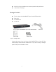
One DC fan for good ventilation and to increase system heat sink performance 19 inch Rack mount design Package Contents The 16 or 24-port 10/100/1000BASE-T plus 2 Combo SFP Slots Switch Power Cord Four Rubber Feet User Manual The 16 or 24-port 10/100/1000BASE-T plus 2 Combo SFP Slots Switch User Guide Power Cord Rubber Feet Figure 1-1. Package Contents Compare the contents of your 16 or 24-port 10/100/1000BASE-T plus 2 Combo SFP Slots Switch package with the standard checklist above.
2. Hardware Description This Section describes the hardware of the 16 or 24-port 10/100/1000BASE-T plus 2 Combo SFP Slots Switch.
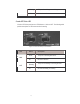
Rear Panel The 3-pronged power plug, on/off switch, and Ventilation fan are located at the rear Panel of the 16 or 24-port 10/100/1000BASE-T plus 2 Combo SFP Slots Switch as shown in Figure 2-2. The Switch will work with AC in the range 100-240V AC, 50-60Hz. Figure 2-2. Rear panel of the 24-port 10/100/1000BASE-T plus 2 Combo SFP Slots Switch LED Indicators The LED Indicators gives a real-time indication of system operating statuses.
Blinking The port is receiving or transmitting data. Off No device attached. Table 2-1. The Descriptions of LED Indicators Combo SFP Slots LED 2 Combo SFP Slots ports have two LED indicators – LNK and ACT. The following table provides descriptions of LEDs status and their meaning. Figure 2-4. Combo SFP Slots port LED Indicators LED Status Description Green The port is connecting with device. Off No device attached. LNK Green ACT (Blinking) Off The port is transmitting or receiving the data.
3. Installation This section shows the installation procedures of the switch. Set the Switch on a sufficiently large flat space with a power outlet nearby. The surface where you put your Switch should be clean, smooth, level, and sturdy. Make sure there is enough clearance around the Switch to allow attachment of cables, power cord and air circulation. Attaching Rubber Feet • Make sure mounting surface on the bottom of the Switch is grease and dust free. • Remove adhesive backing from your Rubber Feet.
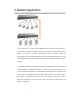
4. Network Application You can use the 16 or 24-port 10/100/1000BASE-T plus 2 Combo SFP Slots Switch to connect servers, switches, workstation, and PCs to each other by connecting these devices directly to the Switch. The Switch automatically learns node address, which are subsequently used to filter and forward all traffic based on the destination address. You can use Gigabit fiber port to connect with fiber network that extend the Ethernet network to fiber network.
5. Troubleshooting The Switch can be easily monitored through panel indicators to assist in identifying problems. This section describes common problems you may encounter and where you can find possible solutions. Diagnosing LED Indicator If Link indicator does not light up after connection, you may check whether network interface (e.g., a network adapter card on the attached device), network cable, or switch port is defective or not. Verify that the switch and attached device are power on.
6. Technical Specification The following table provides the technical specification of the 16 or 24-port 10/100/1000BASE-T plus 2 Combo SFP Slots Switch. IEEE802.3 10BASE-T IEEE802.3u 100BASE-TX Standard IEEE802.3z Gigabit fiber IEEE802.
Consumption Operation 0C to 45C (32F to 113F) Temperature Operation 10% to 90% (Non-condensing) Humidity Dimension 440mm(W) x 161mm(D) x 44mm (H) EMI & Safety FCC Class A, CE, UL, CE/EN60950 6475 City West Pkwy Eden Prairie, MN 55344 Tel.: +1.952.941.7600 techsupport@transition.