Installation & Operator’s Manual SEC8 8,000 lbs. SEC95 9,5000 lbs. SEC12 12,000 lbs. SEC15 15,000 lbs. 77-53141W (SYNTHETIC ROPE) 77-50141W (STEEL CABLE) 76-53246BW (SYNTHETIC ROPE) 76-50246BW (STEEL CABLE) 76-53251BW (SYNTHETIC ROPE) 76-50251BW (STEEL CABLE) 76-53260W (SYNTHETIC ROPE) 76-50260W (STEEL CABLE) SEC4500 76-50115BW (STEEL CABLE) 4,500 lbs. 2121 BLOUNT ROAD POMPANO BEACH, FL 33069 USA MILEMARKER.COM INFO@MILEMARKER.COM 800.886.
TABLE OF CONTENTS Safety Warnings.................................... 2 Precautions........................................... 3 Getting Started: Unpacking Your Winch..................... 4 Winch Mounting............................... 4 Clocking Instructions............................ 5 Control Box Installation......................... 6 Wiring Instructions............................... 8 Winch Operation................................... 9 Winching Tips & Techniques............... 10 Winch Maintenance.
SAFETY WARNINGS 1. L EARN TO USE YOUR MILE MARKER WINCH: A) After winch has been installed, take some time and practice using it so you will be familiar with ALL OPERATIONS. Periodically check the winch installation to ensure that all bolts are tight. B) To ensure proper operation, carefully inspect for any damaged parts before operating the winch. 2. K EEP WINCHING AREA CLEAR: Do not allow people to remain in the area during winching operations.
PRECAUTIONS 1. K eeps hands and body away from Fairlead (cable intake slot) when operating. 2. Secure vehicle in position before using winch. 3. D o not exceed winch load weight capacity (see Winch Specifications). 4. Be certain winch is properly bolted to a structure (or vehicle) that can hold the winch load. 5. Always use proper couplings when connecting winch cable hook to load. 6. Do not lift items vertically. The winch was designed for horizontal use only. 7.
GETTING STARTED Unpacking Your Winch Unpack your new Mile Marker winch and ensure that all the parts are included by referring to parts list and exploded view drawings provided in this manual. NOTE: If you find any missing or broken parts, please call Mile Marker as soon as possible at the number present on the front page of this manual. Winch Mounting NOTE: Mile Marker recommends the use of its mounting systems for proper winch installation and optimum winch performance.
CLOCKING INSTRUCTIONS Winch gear housing can be clocked in 8 positions enabling the user to position the clutch lever at 8 equidistant locations (0°, 45°, 90°….360°). 1. Remove Gear Housing from Tie Bars (Fig. 1-2). 2. Remove the 8 bolts in the Gear Housing Leg (Fig. 1-3). 3. Separate Leg and Gear Housing. A slight tap with a hammer might be needed (Fig. 1-4). 4. P lace Gear Housing Leg in the angle desired and screw in bolts (Fig. 1-5). Torque to spec.
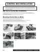
CONTROL BOX INSTALLATION NOTE: Your Mile Marker Control Box can either be mounted to the winch or in a remote location. However, Mile Marker recommends you to mount it to the winch following the instructions below. If you choose to mount it in a remote location, please ensure that: (a) the location does not interfere with any vehicle’s moving/functioning parts, and (b) you use electrical cables with similar or better specifications as that provided by Mile Marker.
Mounting Control Box on Tiebars 1. Mount the control box to mounting brackets using 10 mm wrench (Fig 2-8). 2. Mount control box on the tie bars by attaching front end first and pushing down to snap in the back end (Fig. 2-9). 3. Locate the two extra pieces for the tie bars mounting brackets (Fig. 2-10). 4. Screw in these pieces to the rear side of the tie bar bracket using a Philips Head Screw Driver (Fig. 2-11). 2-8: Install the mounting bracket to the bottom of the control box with a 10mm wrench.
WIRING INSTRUCTIONS Wiring the Control Box 1. Slips the boots onto pertinent cables and make electrical connection in accordance with the schematic on following page. Slide the boots onto all the electrical connections made (figs. 2-12 through 2-14). 2. Run battery power cables carefully under hood of vehicle, avoiding interference with moving parts and abrasion points which could potentially cause electrical short. 3.
WINCH OPERATION Operational Instructions 1. Disengage the clutch by moving the Clutch Lever to Disengage Position (or Freespool mode) (Fig. 3-1). 2. Free Spool the cable and connect to the desired anchor point (self recovery) or vehicle being recovered. 3. Fully Engage the clutch by moving the Clutch Lever to Engage Position (Fig. 3-1). 4. Lift the protective boot covering the hand control plug-in. Insert the hand control plug. 5. Rotate the red Kill Switch from the “OFF” position, to the “ON” position.
WINCHING TIPS & TECHNIQUES Winching Tips and Use of a Snatch Block • Use OEM tow hooks, recovery eyes or a clevis mount for attachment of a tow strap or winch cable. Warning: Never use a ball and/or ball mount as an anchor point for tow strap or winch cable. Severe personal injury or death could occur. •Always heed all winch manufacturer’s recommendations, cautions, and warnings. • Attach return cable to tow hook or recovery eye when using a snatch block.
Self Recovery 1. Always attempt to get the cable as straight as possible to the direction of the vehicle. It is acceptable to start a pull at an angle if it is obvious that the vehicle will turn towards the hook anchoring point. Turning the steering wheel will assist the process. It is recommended that the driver is in the vehicle. 2. Make sure hand brake and foot brake are free and that the transmission is in neutral. 3.
WINCH MAINTENANCE • All moving parts within the Electric Winch have been lubricated using high temperature lithium grease at the factory. No further internal lubrication is required for the life of the winch. •Lubricate the cable periodically using light penetrating oil. • Electrical connections may corrode over a period of time due to environmental changes. This may result in reduced performance of the winch or even possible electrical shorting.
WINCH FEATURES & SPECS FEATURES: •4.
WINCH FEATURES & SPECS FEATURES: SPECIFICATIONS (9.5K): SPECIFICATIONS (12K): •Powerful Series Wound Motor •Rugged Planetary Gear Sets •Clockable Gear Housing •Fast Line Speeds •Submersible, 500 Amp Solenoid •Automatic Load Holding Brake •Corrosion Resistant Stainless Steel Fasteners • 100’ of Synthetic Rope or Steel Cable • Aluminum Hawse or Roller Fairlead • Waterproof •Handheld Remote Control Gear Train 3 Stage planetary Gear Train Gear Ratio 296:1 Gear Ratio 296:1 Motor Series wound, 4.
WINCH FEATURES & SPECS FEATURES: •6.
PARTS BREAKDOWN & ASSEMBLY ITEM 1 2 3 4 5 6 7 8 9 10 11 12 13 14 15 16 17 18 19 20 21 22 23 24 25 26 PAGE 16 QTY 1 16 16 1 4 4 2 1 1 1 1 1 1 1 1 1 1 1 1 2 2 2 1 1 1 1 PART# 77-50141W-01 77-50141W-02 77-50141W-03 77-50141W-04 77-50141W-05 77-50141W-06 77-50141W-07 77-50141W-08 77-50141W-09 77-50141W-10 77-50141W-11 77-50141W-12 77-50141W-13 77-50141W-14 77-50141W-15 77-50141W-16 77-50141W-17 77-50141W-18 77-50141W-19 77-50141W-20 77-50141W-21 77-50141W-22 77-50141W-23 77-50141W-24 77-50141W-25 77-50141W-
PARTS BREAKDOWN & ASSEMBLY with Synthetic Rope ITEM 1 2 3 4 5 6 7 8 9 10 11 12 13 14 15 16 17 18 19 20 21 22 23 24 25 PAGE 17 QTY 1 16 16 1 4 4 2 1 1 1 1 1 1 1 1 1 1 1 1 2 2 2 1 1 1 PART# 77-50141W-01 77-50141W-02 77-50141W-03 77-50141W-04 77-50141W-05 77-50141W-06 77-50141W-07 77-50141W-08 77-50141W-09 77-50141W-10 77-50141W-11 77-50141W-12 77-50141W-13 77-50141W-14 77-50141W-15 77-50141W-16 77-50141W-17 77-50141W-18 77-50141W-19 77-50141W-20 77-50141W-21 77-50141W-22 77-50141W-23 77-50141W-24 77-50141W
PARTS BREAKDOWN & ASSEMBLY ITEM 1 2 3 4 5 6 7 8 9 10 11 12 13 14 15 16 17 18 19 20 21 22 23 24 25 26 PAGE 18 QTY 1 16 16 1 4 4 2 1 1 1 1 1 1 1 1 1 1 1 1 2 2 2 1 1 1 1 PART# 77-50141W-01 77-50141W-02 77-50141W-03 77-50141W-04 77-50141W-05 77-50141W-06 77-50141W-07 77-50141W-08 77-50141W-09 77-50141W-10 77-50141W-11 77-50141W-12 77-50141W-13 77-50141W-14 77-50141W-15 76-50256BW-16 76-50256BW-17 77-50141W-18 77-50141W-19 77-50141W-20 77-50141W-21 77-50141W-22 77-50141W-23 77-50141W-24 77-50141W-25 77-50141
PARTS BREAKDOWN & ASSEMBLY ITEM 1 2 3 4 5 6 7 8 9 10 11 12 13 14 15 16 17 18 19 20 21 22 23 24 25 26 PAGE 19 QTY 1 16 16 1 4 4 2 1 1 1 1 1 1 1 1 1 1 1 1 2 2 2 1 1 1 1 PART# 77-50141W-01 77-50141W-02 77-50141W-03 77-50141W-04 77-50141W-05 77-50141W-06 77-50141W-07 77-50141W-08 77-50141W-09 77-50141W-10 77-50141W-11 77-50141W-12 77-50141W-13 77-50141W-14 76-50256BW-15 76-50256BW-16 76-50256BW-17 77-50141W-18 77-50141W-19 77-50141W-20 77-50141W-21 77-50141W-22 77-50141W-23 77-50141W-24 77-50141W-25 77-5014
PARTS BREAKDOWN & ASSEMBLY ITEM 1 2 3 4 5 6 7 8 9 10 11 12 13 14 15 16 17 18 19 20 21 22 23 24 25 26 PAGE 20 QTY 1 16 16 1 4 4 2 1 1 1 1 1 1 1 1 1 1 1 1 2 2 2 1 1 1 1 PART# 77-50141W-01 77-50141W-02 77-50141W-03 77-50141W-04 77-50141W-05 77-50141W-06 77-50141W-07 77-50141W-08 77-50141W-09 77-50141W-10 77-50141W-11 77-50141W-12 77-50141W-13 77-50141W-14 76-50256BW-15 76-50256BW-16 76-50256BW-17 77-50141W-18 77-50141W-19 77-50141W-20 77-50141W-21 77-50141W-22 76-50141W-23 77-50141W-24 77-50141W-25 77-5014
PARTS BREAKDOWN & ASSEMBLY ITEM 1 2 3 4 5 6 7 8 9 10 11 12 13 14 15 16 17 18 19 20 21 22 23 24 25 26 27 28 PAGE 21 QTY 1 16 16 1 4 4 2 1 1 1 1 1 1 1 1 1 1 1 1 2 2 2 1 1 1 1 1 1 PART# 77-50141W-01 77-50141W-02 77-50141W-03 77-50141W-04 77-50141W-05 77-50141W-06 77-50141W-07 77-50141W-08 77-50141W-09 77-50141W-10 77-50141W-11 77-50141W-12 77-50141W-13 77-50141W-14 76-50256BW-15 76-50256BW-16 76-50256BW-17 77-50141W-18 77-50141W-19 77-50141W-20 77-50141W-21 77-50141W-22 76-50141W-23 77-50141W-24 77-50141W-
WARANTY INFORMATION Limited 2-Year Electric Winch Warranty Mile Marker, Industries offers a limited two (2) year warranty to the original retail purchaser for each new Mile Marker electric winch, used as a recreational recovery winch only, against manufacturing defects in workmanship and materials on all mechanical components. Electrical components consisting of motors, solenoids, wiring, wire connectors and associated parts have a limited one (1) year warranty.
2121 BLOUNT ROAD POMPANO BEACH, FL 33069 USA 800.886.8647 MILEMARKER.COM INFO@MILEMARKER.