
Installation Guide


WIRING INSTRUCTIONS
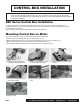
Wiring the Control Box
1. Slips the boots onto pertinent cables and make electrical connection in accordance with the schematic on following page. Slide the boots
onto all the electrical connections made (figs. 2-12 through 2-14).
2. Run battery power cables carefully under hood of vehicle, avoiding interference with moving parts and abrasion points which could
potentially cause electrical short.
3. Attach Black Cable to Negative Battery Terminal (-), followed by Red Cable to Positive Battery Terminal (+) (fig. 2-14). Refer to Winch
Operation Section of this manual for proper functioning; if drum rotates in the incorrect direction when “IN” button is pressed, green and
yellow motor cables need to be switched.
CAUTION: Make sure that all exposed electrical connections are covered with insulation boots to avoid electrical short. Battery
cables should not be drawn taut; leave some slack for cable movement. Also, ensure that they are routed properly
with out any interference with the vehicular components that could potentially damage the cable or cause electrical
short. Long battery cable runs may have significant voltage drops that may cause the winch motor controller to not
operate.
DO NOT CONNECT POWER CABLES TO BATTERY
UNTIL FINAL STEP OF INSTALLATION!
2-12: Complete Wiring Schematic: SEC8
2-14: Complete Wiring to Battery
2-13: Black Cables (ground): Remove bolt, Attach both large and small
cables, and return bolt to motor.
2121 Blount Road Pompano Beach, FL 33069 MileMarker.com 1.800.886.8647PAGE 8