
User Manual
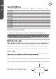


Temperature calibration
f
5
millnorway.com
EN
(Can be done even if you are connected to WiFi)
5 seconds for automatic confirmation.
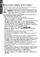
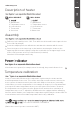
Description of heater
MILL INVISIBLE MILL GLASS
A B
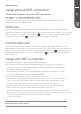
Assembly
2. Wall bracket
3. Temperature sensor
4. Heat emission
5. Thermostat
6. Steel front
2. Wall bracket
3. Temperature sensor
4. Heat emission
5 Thermostat
6. Glass front
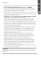
It may occur deviation between the temperature registered by the heater and the
actual temperature in the room. This can be caused by several reasons, however, the
most common is that the heater is placed in a fair distance from where you usually
reside. When you set the temperature to for example 22 degrees, it is only natural that
you expect the same temperature where your sofa is placed for instance. However,
the temperature sensor is placed on the product itself, and therefore a deviation in
temperature may occur. To adjust this, all Mill heaters are equipped with a calibration
function, which enables you to adjust the temperature registered by the heater. N.B! The
room must have achieved a stable temperature before any calibration.
Drill holes in the wall for holes 1 & 2. Then drill holes in the wall for the topmost holes
(holes 3 & 4 by using 6)
Insert the wall plugs into the drilled holes and attach the bracket with 4 screws
Place the heater on the lower lugs on the bracket, then hang the heater on the
upper lugs (lift the heater slightly to align the heater with for the upper lugs). Screw
in the locking screws on the top of the bracket (clockwise)
Attention! Horizontal placement only
If the heater uses power (for example, when it heats up), the power indicator is on.