
Owner's manual


4
HV-3D
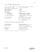
HV-3D REAR PANEL
(1) CONVENTIONAL MIC INPUTS "48V IN (1 - 8)"
Conventional 3-pin female XLR input jacks for use with all conventional balanced microphones, both phantom
and non-phantom powered. Provides +48V Phantom powering. Standard input impedance is approximately
6,200 ohms. Pin 1 is ground. Pin 2 is positive polarity. Pin 3 is negative polarity. Connector contacts are Neutrik
Galvatronic gold plated. It is suggested that XLR cable connectors used with the HV-3D employ identical plating.
(2) HIGH VOLTAGE MIC INPUTS "130V IN (1 - 8)"
Four pin female XLR connector for use only with B&K (DPA) models 4003, 4004, 4009, and 4012 micro-
phones. On HV-3D units without this option, a metal plate will cover the unused XLR holes. Pin 1 is
ground. Pin 2 is not connected. Pin 3 is +130 Volts DC power, and pin 4 is unbalanced audio signal. Connecting
anything other than the above listed B&K (DPA) models to this connector may result in serious damage to
microphone, the HV-3D unit, or both. Connector contacts are Neutrik Galvatronic gold plated. It is suggested
that XLR cable connectors used with the HV-3D employ identical plating.
(3) LINE LEVEL OUTPUTS "OUT (1 - 8)"
Conventional three pin male XLR connectors providing balanced, line level microphone output. Pin 1 is
ground. Pin 2 is positive polarity. Pin 3 is negative polarity. The line level output is capable of driving 600 ohm
loads and long, high capacitance cables. Outputs may be configured in an unbalanced configuration by either
grounding one of the audio polarities (pin 2 or pin 3), or taking one audio polarity directly as an unbalanced
signal. In the former configuration, the output is automatically increased by 6 dB. Connector contacts are Neutrik
Galvatronic gold plated. It is suggested that XLR cable connectors used with the HV-3D employ identical plating.
(4) EARTH/AUDIO GROUND JUMPER
A barrier terminal which ties earth ground to audio ground. If ground "hum" loops are experienced when
using the HV-3D, removing this jumper may help. Using this jumper to lift ground, the integrity of the chassis/
earth ground connection is never compromised. Do not defeat the earth grounding pin on the AC plug.
(5) AC VOLTAGE MAINS SELECTION "100-120" or "200-240"
A power entry module with a removable fuse holder block. This fuse holder block is selectable for 100 to
120 Volt or 200 to 240 Volt worldwide mains powering. The fuse block contains two fuses — one fuse is
in series with the hot power line while the other fuse is in series with the neutral power line. Both fuses
must be installed. To change the mains voltage selection, remove IEC power connector and assure that the
HV-3D is not connected to mains power. With a non-conductive tool, gently pry the fuse block away from
the power entry module. Remove the two fuses and replace both with type as shown below. Slide out the
internal PC Board, turn it over, and reinsert the PCB so that the desired AC mains voltage appears in the viewing
window. Double check that the fuses installed correspond to the AC mains voltage range which appears in the
viewing window. Gently push the fuse block back until flush and snug.
FUSES:
For 100-120 VAC mains 2 ch, use 5 x 20 mm,400 mA, slow blow, 250 V, Littelfuse 218 or equiv.
For 100-120 VAC mains 4 ch, use 5 x 20mm, 630 mA, slow blow, 250 V, Littelfuse 218 or equiv.
For 100-120 VAC mains 8ch, use 5 x 20 mm, 1.00 A, slow blow, 250 V, Littelfuse 218 or equiv.
For 200-240 VAC mains 2 ch, use 5 x 20 mm, 200 mA, slow blow, 250 V, Littelfuse 218 or equiv.
For 200-240 VAC mains 4 ch, use 5 x 20 mm, 315 mA, slow blow, 250 V, Littelfuse 218 or equiv.
For 200-240 VAC mains 8 ch, use 5 x 20 mm, 500 mA, slow blow, 250 V, Littelfuse 218 or equiv.