
Quick Reference Guide Instruction Manual


Millennia Media HV-3C and HV-3D
022808
page 2 of 2
HV-3C
HV-3D
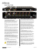
Rear Panel
1. CONVENTIONAL MIC INPUTS "48V IN "
Conventional 3-pin female XLR input jacks for use with
all conventional balanced microphones, both phantom
and non-phantom powered. Provides +48V Phantom
powering. Standard input impedance is approximately
6,200 ohms. Pin 1 is ground. Pin 2 is positive polarity.
Pin 3 is negative polarity.
Connector contacts are Neutrik gold and Super C plated.
It is suggested that XLR cable connectors used with the
HV-3 series preamp employ identical plating to minimize
corrosion if you are not plugging the cables in often.
2. HIGH VOLTAGE MIC INPUTS "130V IN " Four pin
female XLR connector for use only with DPA (B&K)
models 4003, 4004, 4009, and 4012 microphones. On
HV-3 series preamps without this option, a plate will
cover the unused XLR holes. Pin 1 is ground. Pin 2 is not
connected. Pin 3 is +130 Volts DC power and pin 4 is
unbalanced audio signal.
Connecting anything other than the above listed DPA
models to this connector may result in serious damage
to microphone, the HV-3 series preamp, or both.
Connector contacts are Neutrik gold and Super C plated.
It is suggested that XLR cable connectors used with the
HV-3 series preamp employ identical plating to minimize
corrosion if you are not plugging the cables in often.
3. LINE LEVEL OUTPUTS "OUT"
Conventional three pin male XLR connectors providing
balanced, line level microphone output. Pin 1 is ground.
Pin 2 is positive polarity. Pin 3 is negative polarity. The
line level output is capable of driving 600 ohm loads and
long, high capacitance cables. Outputs may be
configured in an unbalanced configuration by either
grounding one of the audio polarities (pin 2 or pin 3), or
taking one audio polarity directly as an unbalanced
signal (recommended). In the former configuration, the
output is automatically decreased by 6 dB. Connector
contacts are Neutrik gold and Super C plated.
4. AC VOLTAGE MAINS SELECTION "100-120" or
"200-240" A power entry module with a removable fuse
holder block. This fuse holder block is selectable for 100
to 120 Volt or 200 to 240 Volt worldwide mains
powering.
The fuse block contains two fuses — one fuse is in series
with the hot power line while the other fuse is in series
with the neutral power line. Both fuses must be
installed. To change the mains voltage selection, remove
IEC power connector and assure that the HV-3 series
preamp is not connected to mains power.
With a non-conductive tool, gently pry the fuse block
away from the power entry module. Remove the two
fuses and replace both with type as shown below. Orient
the fuse block so that the proper voltage is shown and
reinsert into the power entry module.
Double check that the fuses installed correspond to the
AC mains voltage range which is shown on the exterior
panel. Gently push the fuse block back until flush and
snug.
5. FUSES
5 x 20 mm,1000 mA, slow blow, 250 V, Littelfuse 218 or
equiv..
POWER ENTRY "IEC Power Receptacle"
An IEC-type AC line-power receptacle for use with
removable cords. Use only the power cord
provided with the HV-3 series preamp unit or equivalent
U/L approved type SV, SVT, SJ, or SJT AC power supply
cord. Do not defeat the third pin earth ground.
The complete HV-3D and HV-3C manuals are
available on-line:
http://mil-media.com/pdf/hv3d-manual.pdf
http://mil-media.com/pdf/ManualWebHV-3C.pdf
DSD CLK
WC IN
DSD LEFT
WC OUT
DSD RIGHT
AES OUT 1
ADAT/
S/P-DIF
OPTICAL
AES OUT 2 LINE IN FT LINE IN RIGHT CH.2 OUT CH.2 OPT IN CH.1 OUT CH.1 OPT IN
SPDIF OUT
LE
130V130V
CH.1 INCH.2 IN
PUSHPUSH PUSHPUSH
RESERVED FOR ADC
PUSH
PUSH
PUSH
PUSH
PUSH
PUSH
PUSH
PUSH
PUSH
PUSH
PUSH
PUSH
PUSH
PUSH
PUSH
PUSH
12345678
12345678
12345678
48V
IN
130V
IN
OUT
This device complies with Part 1 peration is subject to the following two conditions:
(1) This device may not cause and (2) this device must accept any interference
received, including interference that may cause undesired operation.
For 115 - 240VAC operation, 50-60 Hz. Use only the following fuse types shown:
100 - 120VAC: 2 ch x mA, 4 ch x mA, 8 ch xA, all 250V Litelfuse type 313 slow blow, or equivalent.
200 - 240VAC: 2 ch x mA, 4 ch x mA, 8 ch xxx mA, all 250V Litelfuse type 313 slow blow, or equivalent
5 of the FCC rules. O
harmful interference,
Chassis/Audio
Ground Strap
100 / 115 / 230 Selection
115
1
1
4
2
2
3
4
3
5
5