
Owner`s manual

8
STT-1
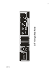
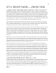
(5) MAIN OUTPUT #2 "MAIN OUT - UNBAL"
Conventional three pin male XLR connector providing unbalanced, line level output from all stages
of the STT-1. Can be used simultaneously with all other outputs. This XLR sits directly above the 1/4"
unbalanced output connector. Pin 1 is ground. Pin 2 is positive polarity. Pin 3 is ground. This output is
all discrete, pure Class-A, and is capable of driving < 600 ohm loads and long, high capacitance cables.
This output should drive a balanced destination with no interface concerns. In the rare instance where a
balanced destination exhibits difficulty with an unbalanced source, use the balanced output (#4 above).
Connector contacts are Neutrik Galvatronic gold plated. It is suggested that XLR cable connectors used
with the STT-1 employ identical plating.
(6) MAIN OUTPUT #3 "MAIN OUT - UNBAL"
Conventional 1/4" female phone connector providing unbalanced, line level output from all stages of the
STT-1. Can be used simultaneously with all other outputs. Tip is signal positive polarity, Sleeve is ground.
This output is all-discrete, pure Class-A and is capable of driving < 600 ohm loads and long, high capaci-
tance cables. This output should drive a balanced destination with no interface concerns. In the rare in-
stance where a balanced destination shows difficulty with an unbalanced source, use the balanced output
(#4 above). This output is paralleled with Output #5 (above).
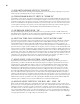
(7) DYNAMICS LINK "Dyn Link"
Conventional RCA-style phono jack providing a connection to the dynamics side chain circuit. Use to
link dual STT-1 units for stereo operation. Any conventional RCA phono cable should work appropri-
ately.
(8) EARTH/AUDIO GROUND JUMPER
A barrier terminal which ties earth ground to audio ground. If ground "hum" loops are experienced when
using the STT-1, removing this jumper may help. Using this jumper to lift ground, the integrity of the
chassis/earth ground connection is never compromised. Do not defeat the earth grounding pin on the AC
plug.
(9) AC VOLTAGE MAINS SELECTION "100-120" or "200-240"
A power entry module with a removable fuse holder block. This fuse holder block is selectable for 100
- 120 Volt or 200 - 240 Volt worldwide mains powering. The fuse block contains two fuses — one fuse is
in series with the hot power line while the other fuse is in series with the neutral power line. Both fuses
must be installed. To change the mains voltage selection, remove IEC power connector and assure that
the STT-1 is not connected to mains power. With a non-conductive tool, gently pry the fuse block away
from the power entry module. Remove the two fuses and replace both with type as shown below. Slide
out the internal PC Board, turn it over, and reinsert the PCB so that the desired AC mains voltage appears
in the viewing window. Double check that the fuses installed correspond to the AC mains voltage range
which appears in the viewing window. Gently push the fuse block back until flush and snug.
FUSES:
For 100-120 VAC mains, use two 5 x 20 mm, 1A, slow blow, 250 V, Littelfuse 218 or equiv.
For 200-240 VAC mains, use two 5 x 20 mm, 500 mA, slow blow, 250 V, Littelfuse 218 or equiv.
(10) POWER ENTRY "IEC Power Receptacle"
An IEC-type AC line-power receptacle for use with removable cords. Use only the power cord provided