
User Manual


P.O. Box 159 • West Grove, PA 19390 • 800-220-3343 • 610-869-4422 • Fax: 610-869-4423 • www.milleredge.com
6809 South Harl Ave., Suite A • Tempe, AZ 85283 • 800-887-3343 • 480-755-3565 • Fax: 480-755-3558
Transmitter:
MODEL: MEL-TX20
FCC ID: OYE-MEL315
THIS DEVICE COMPLIES WITH PART 15 OF THE FCC RULES. OPERATIONS IS SUBJECT TO THE FOLLOWING
TWO CONDITIONS.
1) THIS DEVICE MAY NOT CAUSE HARMFUL INTERFERENCE
AND
2) THIS DEVICE MUST ACCEPT ANY INTERFERENCE RECEIVED INCLUDING INTERFERENCE THAT MAY
CAUSE UNDESIRED OPERATION.
8- FCC Compliance
Receiver:
MODEL: MEL-RX20
This equipment has been tested and found to comply with the limits for a Class B digital device, pursuant to Part15 of the FCC Rules.
These limits are designed to provide reasonable protection against harmful interference in a residential installation. This equipment
generates, uses and can radiate radio frequency energy and, if not installed and used in accordance with the instructions, may cause
harmful interference to radio communications. However, there is no guarantee that interference will not occur in a particular installa-
tion. If this equipment does cause harmful interference to radio or television reception, which may be determined by turning the
equipment off and on, the user is encouraged to try to correct the interference by one or more of the following measures:
1- Re-orient or relocate the receiver antenna
2- Increase the separation between the equipment and the receiver
3- Connect the equipment into an outlet on a circuit different from that to which the receiver is connected.
4- Consult the dealer or an experienced radio/TVtechnician for help.
Changes or Modifications Not Expressly Approved By The Party Responsible For Compliance Could Void The User’s
Authority To Operate The Equipment.
7- Appendix:
Miller Edge Terminated Sensing Edge Color Coding:
T2 10K Resistor (Blue band)
T3 Diode/Capacitor (Red band)
* Colored ID tape is located on the Sensing Edge cable.
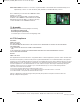
Alarm Power Switch: Provides for connection of optional audible or visual alarm when transmitter battery is low.
Optional: Dry contacts, or +5vdc @ 20 ma. (max) available on the NO & NC relay contacts.
The Low Bat relay is active when the “LOW BAT” LED is
f
lashing or on steady.
With alarm power switched “ON”, you will have 5VDC
available on the “LOW BAT” terminal between NC & NO.
With alarm power turned “OFF”, you will have dry relay
c
ontacts available on the “LOW BAT” terminals.
MEL-K20_Inst_20140708
MEL-K20_Inst_20140708_WPE Instuctions 7/16/14 12:01 PM Page 4