OM-2248 213 990E 2007−02 Processes Air Plasma Cutting and Gouging Description Air Plasma Cutter R Spectrum 125C And ICE-12C Torch Visit our website at www.MillerWelds.
From Miller to You Thank you and congratulations on choosing Miller. Now you can get the job done and get it done right. We know you don’t have time to do it any other way. That’s why when Niels Miller first started building arc welders in 1929, he made sure his products offered long-lasting value and superior quality. Like you, his customers couldn’t afford anything less. Miller products had to be more than the best they could be. They had to be the best you could buy.
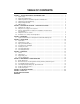
TABLE OF CONTENTS SECTION 1 − SAFETY PRECAUTIONS - READ BEFORE USING . . . . . . . . . . . . . . . . . . . . . . . . . . . . . . . . . . 1-1. Symbol Usage . . . . . . . . . . . . . . . . . . . . . . . . . . . . . . . . . . . . . . . . . . . . . . . . . . . . . . . . . . . . . . . . . . . . . . . . 1-2. Plasma Arc Cutting Hazards . . . . . . . . . . . . . . . . . . . . . . . . . . . . . . . . . . . . . . . . . . . . . . . . . . . . . . . . . . . . 1-3.
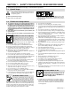
SECTION 1 − SAFETY PRECAUTIONS - READ BEFORE USING pom _4/05 Y Warning: Protect yourself and others from injury — read and follow these precautions. 1-1. Symbol Usage Means Warning! Watch Out! There are possible hazards with this procedure! The possible hazards are shown in the adjoining symbols. Y Marks a special safety message. . Means “Note”; not safety related. This group of symbols means Warning! Watch Out! possible ELECTRIC SHOCK, MOVING PARTS, and HOT PARTS hazards.
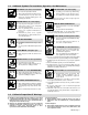
D D D EXPLODING PARTS can injure. D D D On inverter power sources, failed parts can explode or cause other parts to explode when power is applied. Always wear a face shield and long sleeves when servicing inverters. D FLYING SPARKS can cause injury. D Sparks and hot metal blow out from the cutting arc. Chipping and grinding cause flying metal. D Wear approved face shield or safety goggles with side shields. Wear proper body protection to protect skin.
1-3. Additional Symbols For Installation, Operation, And Maintenance HOT PARTS can cause severe burns. D Do not touch hot parts bare handed. D Allow cooling period before working on torch. D To handle hot parts, use proper tools and/or wear heavy, insulated welding gloves and clothing to prevent burns. FALLING UNIT can cause injury. D Use lifting eye to lift unit only, NOT running gear, gas cylinders, or any other accessories. D Use equipment of adequate capacity to lift unit.
1-5. Principal Safety Standards Safety in Welding, Cutting, and Allied Processes, ANSI Standard Z49.1, from Global Engineering Documents (phone: 1-877-413-5184, website: www.global.ihs.com). Code for Safety in Welding and Cutting, CSA Standard W117.2, from Canadian Standards Association, Standards Sales, 178 Rexdale Boulevard, Rexdale, Ontario, Canada M9W 1R3. Recommended Practices for Plasma Arc Cutting, American Welding Society Standard AWS C5.
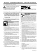
SECTION 2 − CONSIGNES DE SÉCURITÉ − LIRE AVANT UTILISATION pom_fre 5/04 2-1. Signification des symboles Signifie Mise en garde ! Soyez vigilant ! Cette procédure présente des risques de danger ! Ceux-ci sont identifiés par des symboles adjacents aux directives. Y Identifie un message de sécurité particulier. . Signifie NOTA ; n’est pas relatif à la sécurité.
D Isoler la pince de masse quand pas mis à la pièce pour éviter le contact avec tout objet métallique. Il y a DU COURANT CONTINU IMPORTANT dans les convertisseurs après la suppression de l’alimentation électrique. D Arrêter les convertisseurs, débrancher le courant électrique, et décharger les condensateurs d’alimentation selon les instructions indiquées dans la partie entretien avant de toucher les pièces. Tableau 1.
LES BOUTEILLES peuvent exploser si elles sont endommagées. Les bouteilles de gaz contiennent du gaz sous haute pression. Si une bouteille est endommagée, elle peut exploser. Puisque les bouteilles de gaz font habituellement partie d’un processus de travail des métaux, assurez−vous de les manipuler correctement. D Protégez les bouteilles de gaz comprimé contre la chaleur excessive, les chocs mécaniques, le laitier, la flamme, les étincelles et l’arc.
2-4. Principales normes de sécurité Safety in Welding and Cutting, norme ANSI Z49.1, de l’American Welding Society, 550 N.W. Lejeune Rd, Miami FL 33126 Safety and Health Sandards, OSHA 29 CFR 1910, du Superintendent of Documents, U.S. Government Printing Office, Washington, D.C. 20402. Recommended Safe Practice for the Preparation for Welding and Cutting of Containers That Have Held Hazardous Substances, norme AWS F4.1, de l’American Welding Society, 550 N.W.
SECTION 3 − DEFINITIONS 3-1.
SECTION 4 − INSTALLATION 4-1. Specifications Primary Volts Primary Amperes 120 20.32 (0.25*) Primary Service (Recommended) 20A Secondary Volts (DC) Secondary Amperes 110 12 KW 2.01 KVA 2.44 Rated Cutting Capacity 0.25 in (6.4 mm) At 6 IPM (2.5 mm/s) Power Factor Max** OCV (DC) 0.82 335 *While idling **10% High line condition 4-2. Specifications For Torch Air-cooled torch for plasma arc cutting (PAC) 35% duty cycle Compressor output: 1.2 scfm (28.
4-4. Torch Dimensions And Weight 8-3/8 in (213 mm) 1 in (25 mm) 1-3/8 in (35 mm) 3.0 lb (1.4 kg) Ref. 801 397-A 4-5. Selecting A Location 6-3/4 in (171 mm) Dimensions And Weight 17 in (432 mm) 44 lb (20 kg) − Non-CE Models 52 lb (24 kg) − CE Models 18 in (457 mm) 1 1 Movement Lifting Handle Use handle to lift unit. 2 2 Hand Cart Use cart or similar device to move unit.
4-6. Connecting Work Clamp 1 2 1 Work Clamp Workpiece Connect work clamp to a clean, paint-free location on workpiece, as close to cutting area as possible. 2 802 463-A 4-7. Connecting Input Power Check input voltage available at site. 1 1 2 3 4 Grounded 120 VAC Receptacle (Non-CE Models) A 120 volt, 20 ampere individual branch circuit protected by time-delay fuses or circuit breaker is required (see Section 4-1). 2 Plug From Unit Select extension cord of 12 AWG for up to 53 ft (16 m).
SECTION 5 − OPERATION 5-1. Controls 1 2 OFF POWER CUP ON TEMP INPUT VOLTAGE 3 1 2 Power Switch Power Light 3 Trouble Light Trouble light comes on for the following conditions: Use light to tell if unit is energized and ready to operate. Light goes off if input power is not with specified range (see trouble light information).
5-3.
5-4. Sequence Of Operation . Moisture from the compressor will form in the air line and at EXAMPLE Of Cutting Operation the torch. It will be normal to sometimes see moisture come out the end of the torch. The pilot arc starts immediately when trigger is pressed. For shielded cutting, place drag shield on edge of metal. For non-shielded cutting (non-CE only), use 1/8 in (3.2 mm) standoff distance (dragging tip will reduce tip life). Adjust torch speed so sparks go thru metal and out bottom of cut.
SECTION 6 − MAINTENANCE & TROUBLESHOOTING 6-1. Routine Maintenance Y Disconnect power before maintaining. n = Check Z = Change ~ = Clean * To be done by Factory Authorized Service Agent . Maintain more often during severe conditions.
6-2. Overload Protection: Trouble Light And Checking Shield Cup Shutdown System If certain problems occur, the trouble light comes on, and output stops. 1 Trouble Light a Turn power Off, and check shield cup connection (see Item 2 below). Power must be reset whenever the cup shutdown is activated. CUP 1 TEMP INPUT VOLTAGE Check shield cup shutdown system once a week. Checking Torch Shield Cup Shutdown System Power source Power switch must be reset whenever cup shutdown system is activated.
6-3. Torch And Work Cable Connections If torch or work cable needs to be removed or replaced, proceed as follows: 4 5 7 8 6 Turn power Off, and disconnect input power plug from receptacle. Remove wrapper from unit. Torch Connections Remove existing torch cable from unit. 1 5 Strain Relief 2 Torch Cable Insert cable through strain relief. Slide strain relief nut onto torch cable, but do not tighten. 2 6 1 3 Air Line Connector Install air line connector into compressor fitting.
6-4. Checking/Replacing Retaining Cup, Tip, And Electrode Overtightening will strip threads. Do not overtighten retaining cup during assembly. Do not cross-thread parts causing stripping. Use care during torch assembly and parts replacement. Inspect shield cup, tip, and electrode for wear before cutting or whenever cutting speed has been significantly reduced. Do not operate torch without a tip or electrode in place. Be sure to use genuine replacement parts.
6-5. Troubleshooting Power Source Is input power connected to correct line voltage? No Connect unit to proper input voltage. (see Section 4-7). Yes Is Power switch in the On position? No Place Power switch in the On position. (see Section 5-1). Does pilot arc ignite? No Press torch trigger and check if pilot arc ignites. Check torch consumables. *Check torch connections, relay CR1, compressor, and torch. Yes No * Check Power switch S1, relay CR2, and thermistor R1.
6-6. Troubleshooting Torch Does arc go on and off while cutting? Yes Torch travel speed too slow; increase travel speed (see Section 5-2). Clean or replace torch consumables as necessary (see Section 6-4). Be sure work clamp is securely attached to workpiece. Go to Section 6-5. Be sure work clamp is securely attached to workpiece. Make sure drag shield contacts metal while cutting. Clean or replace torch consumables as necessary (see Section 6-4). Go to Section 6-5.
SECTION 7 − ELECTRICAL DIAGRAM 230 564-A Figure 7-1.
Notes OM-2248 Page 23
SECTION 8 − PARTS LIST . Hardware is common and not available unless listed. 3 4 5 1 2 6 7 8 9 35 11 10 34 12 36 33 37 13 31 30 32 14 15 16 29 28 17 21 18 27 26 25 19 24 20 23 22 803 554-E Figure 8-1.
Item No. Dia. Mkgs. Part No. Description Quantity Figure 8-1. Main Assembly . . . . . . . . . . . . . . . . . . . 220 328 . . COVER ASSY (including) . . . . . . . . . . . . . . . . . . . . . . . . . . . . . . . . . . . . . . . . . . . 1 . . . . . . . . . . . . . 204 326 . . . . CONSUMABLE STORAGE BOX w/DOOR (including) . . . . . . . . . . . . . . . . . 2 . . . . . . . . . . . . . 089 899 . . . . . . LATCH, slide . . . . . . . . . . . . . . . . . . . . . . . . . . . . . . . . . . . . . . . . . . . . . .
1 Item Part No. No. 1 183 427 2 3 4 5 6 171 248 196 931 196 930 196 932 185 833 190 220 169 231 195 172 2 3 6 Description Handle Assy, left and right w/screws (1) Pushbutton Switch (1) Leads, 20ft (1) Label, ICE-12C (1) Main Body (1) Switch Assy w/Spring (1) Spring, trigger assy (1) Grease, silicone (1) Torch, replacement (1) 5 1 4 Figure 8-2. Torch, ICE-12C S and CE markings only apply when the torch is used with shielded parts: retaining cup (197 567) and drag shield (196 929).
Effective January 1, 2006 (Equipment with a serial number preface of “LG” or newer) Warranty Questions? Call 1-800-4-A-MILLER for your local Miller distributor. Your distributor also gives you ... Service You always get the fast, reliable response you need. Most replacement parts can be in your hands in 24 hours. Support Need fast answers to the tough welding questions? Contact your distributor. The expertise of the distributor and Miller is there to help you, every step of the way.
Owner’s Record Please complete and retain with your personal records. Model Name Serial/Style Number Purchase Date (Date which equipment was delivered to original customer.) Distributor Address City State Zip For Service Contact a DISTRIBUTOR or SERVICE AGENCY near you. Always provide Model Name and Serial/Style Number. Contact your Distributor for: Welding Supplies and Consumables Options and Accessories Personal Safety Equipment Service and Repair Miller Electric Mfg. Co.