OM-223 194 June 2005 Effective with serial number 210 344 Processes MIG (GMAW) Welding Flux Cored (FCAW) Welding Description Arc Welding Power Source Wire Feeder R Migmatic 271/273/333/383 Visit our website at www.MillerWelds.
From Miller to You Thank you and congratulations on choosing Miller. Now you can get the job done and get it done right. We know you don’t have time to do it any other way. That’s why when Niels Miller first started building arc welders in 1929, he made sure his products offered long-lasting value and superior quality. Like you, his customers couldn’t afford anything less. Miller products had to be more than the best they could be. They had to be the best you could buy.
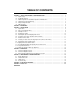
TABLE OF CONTENTS SECTION 1 − SAFETY PRECAUTIONS - READ BEFORE USING . . . . . . . . . . . . . . . . . . . . . . . . . . . . . . . . . . . 1-1. Symbol Usage . . . . . . . . . . . . . . . . . . . . . . . . . . . . . . . . . . . . . . . . . . . . . . . . . . . . . . . . . . . . . . . . . . . . . . . . 1-2. Arc Welding Hazards . . . . . . . . . . . . . . . . . . . . . . . . . . . . . . . . . . . . . . . . . . . . . . . . . . . . . . . . . . . . . . . . . . 1-3.
Declaration of Conformity Manufacturer’s Name: ITW WELDING PRODUCTS ITALY S.r.l.
SECTION 1 − SAFETY PRECAUTIONS - READ BEFORE USING som _3/05 Y Warning: Protect yourself and others from injury — read and follow these precautions. 1-1. Symbol Usage Means Warning! Watch Out! There are possible hazards with this procedure! The possible hazards are shown in the adjoining symbols. Y Marks a special safety message. . Means “Note”; not safety related. This group of symbols means Warning! Watch Out! possible ELECTRIC SHOCK, MOVING PARTS, and HOT PARTS hazards.
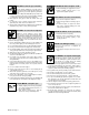
ARC RAYS can burn eyes and skin. Arc rays from the welding process produce intense visible and invisible (ultraviolet and infrared) rays that can burn eyes and skin. Sparks fly off from the weld. D Wear an approved welding helmet fitted with a proper shade of filter lenses to protect your face and eyes when welding or watching (see ANSI Z49.1 and Z87.1 listed in Safety Standards). D Wear approved safety glasses with side shields under your helmet.
1-3. Additional Symbols For Installation, Operation, And Maintenance FIRE OR EXPLOSION hazard. MOVING PARTS can cause injury. D Do not install or place unit on, over, or near combustible surfaces. D Do not install unit near flammables. D Do not overload building wiring − be sure power supply system is properly sized, rated, and protected to handle this unit. D Keep away from moving parts such as fans. D Keep all doors, panels, covers, and guards closed and securely in place.
1-5. Principal Safety Standards Safety in Welding, Cutting, and Allied Processes, ANSI Standard Z49.1, from Global Engineering Documents (phone: 1-877-413-5184, website: www.global.ihs.com). Boulevard, Rexdale, Ontario, Canada M9W 1R3 (phone: 800−463−6727 or in Toronto 416−747−4044, website: www.csa−international.org). Recommended Safe Practices for the Preparation for Welding and Cutting of Containers and Piping, American Welding Society Standard AWS F4.
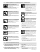
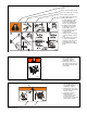
SECTION 2 − DEFINITIONS Warning! Watch Out! There are possible hazards as shown by the symbols. 1 Electric shock can kill. 1.1 Wear dry insulating gloves. Do not touch electrode with bare hand. Do not wear wet or damaged gloves. 1.2 Protect yourself from electric shock by insulating yourself from work and ground. 1.3 Disconnect input plug or power before working on machine. 2 Breathing welding fumes can be hazardous to your health. 2.1 Keep your head out of the fumes. 2.
Warning! Watch Out! There are possible hazards as shown by the symbols. Electric shock from wiring can kill. Disconnect input plug or power before working on machine. Read the Owner’s Manual before working on this machine. 1 Consult rating label for input power requirements, and check power available at the job site − they must match. Read Owner’s Manual and inside labels for connection points and procedures. Move jumper links as shown on inside label to match voltage at job site.
1 1 2 3 4 2 3 4 5 Warning! Watch Out! There are possible hazards as shown by the symbols. Electrical shock from wiring can kill. Read Owner’s Manual before working on this machine Wear approved safety glasses Electrode Positive (Straight Polarity) Place terminal strips as shown. 6 5 6 Electrode Negative (reverse Poalrity) Place terminal strips as shown.
SECTION 3 − INSTALLATION 3-1. Specifications Rated Output Model 100% 60% 20% 271 110 A 20.0 V 150 A 21.0 V 240 A 26 V Max. Open Circuit Voltage Rated Input Amperage at Rated Output 220/230 VAC 50Hz 32 A 3 A* 41 Dimension (mm) Weight (kg) 480 x 800 x 1050 85 Net Wire feed speed range 1.3 mpm to 20 mpm. * While idling Rated Output Model 100% 60% 35% 273 145 A 21.0 V 190 A 23.0 V 240 A 26 V Max.
3-2. Duty Cycle And Overheating Duty Cycle is percentage of 10 minutes that unit can weld at rated load without overheating. If unit overheats, thermostat(s) opens, output stops, and cooling fan runs. Wait fifteen minutes for unit to cool. Reduce amperage or voltage, or duty cycle before welding. Y Exceeding duty cycle can damage unit and void warranty.
3-4. Installing Gas Supply Chain gas cylinder to running gear, wall, or other stationary support so cylinder cannot fall and break off valve. 1 Regulator/Flow Gauge Install so face is vertical. 2 3 Gas Hose Connection Flow Adjust Typical flow rate is 20 cfh (cubic feet per hour). Check wire manufacturer’s recommended flow rate. This flow gauge can be adjusted between 5 and 25 cfh. 1 Argon Gas OR 2 3 CO2 Gas Ref. ST-148 265-B / Ref. ST-149 827-B / Ref. ST-158 697-A 3-5.
3-6. Positoning Jumper Links (230/400V 3-Phase Models) 230 V 400 V 3-7. Electrical Service Guide Migmatic Model 271 Input Voltage 230 230 400 230 400 230 400 Input Amperes at Rated Output 35 23 13 32 19 38 22 Max Recommended Standard Fuse or Circuit Breaker Rating in Amperes 35 23 13 32 19 38 22 ** Input Conductor Size in mm2 4 2.5 2.5 6 4 6 4 4 2.5 2.
3-8. Selecting a Location and Connecting Input Power (1-Phase and 3-Phase) Have only qualified persons make this installation. 1 Rating Label Supply correct input power.
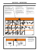
3-9. Installing Drive Rolls and Wire Guide 1 2 Securing Screw Inlet Wire Guide Loosen screw. Slide tip as close to drive rolls as possible without touching. Tighten screw. 3 5 Anti-Wear Guide Install guide as shown. 3 4 2 Drive Roll The drive roll consists of two different sized grooves. The stamped markings on the end surface of the drive roll refers to the groove on the opposite side of the drive roll. The groove closest to the motor shaft is the proper groove to thread.
3-11. Threading Welding Wire and Adjusting Pressure Roll Tension 1 2 3 4 5 6 7 4 7 Wire Spool Welding Wire Inlet Wire Guide Pressure Adjustment Knob Drive Roll Outlet Wire Guide Gun Conduit Cable Lay gun cable out straight. Tools Needed: 1 2 3 5 6 . Hold wire tightly to keep it from unraveling. 6 in (150 mm) Open pressure assembly. Pull and hold wire; cut off end. . Use pressure indicator Tighten scale to set a desired drive roll pressure.
3-12. Using Gun/Cable Holder 1 2 3 2 Press latch down to release and open door. 4 1 Side Panel Latch Cable Holder 4 3 Holster (2) Wrap cable around cable holder, and place gun nozzle into holster. Ref. 802 726-A 3-13. Setting Gun Polarity for Wire Type (Optional) 1 Terminal Cover Protects Polarity Change over terminals from accidental contact. Remove cover to gain access. 3 2 Electrode Positive (DCEP) For solid steel, stainless steel, aluminum, or flux core with gas, wires (GMAW).
SECTION 4 − OPERATION 4-1. Controls for Migmatic 271/273 1 Voltage Control Turn control clockwise to increase voltage. 2 8 2T/4T Trigger Hold Function Latching Torch Trigger 1 7 3 4 5 6 7 2 Turn control clockwise to increase wire feed speed. 8 6 3 Power Switch Work Lead Connection MIG Torch Connection Digital Display Function Button* Wire Feed Speed Control Digital Display* Volts/Amps/Wire Feed Speed with last value hold function.
4-3. Run-In, Burnback (Optional) and Spot Weld Timer Controls 1 Run-In Control* Speed of wire prior to striking a welding arc. This value is a percentage of the set wire for welding. 1 2 Burnback Control* Time that welding wire stays energized after trigger is released. 3 Spot Weld Timer Time that welding arc is active before shutting off automatically. 2 Spot Timer resets after releasing gun trigger.
SECTION 5 − MAINTENANCE &TROUBLESHOOTING 5-1. Routine Maintenance . Maintain more often Y Disconnect power before maintaining. during severe conditions. 3 Months Replace unreadable labels Repair or replace cracked weld cable Clean and tighten weld terminals 6 Months Remove drive roll and carrier. Apply light coat of oil or grease to drive motor shaft. Blow out or vacuum inside. OR Ref. 802 990 5-2. Circuit Breaker CB1 1 Circuit Breaker CB1 CB1 protects the unit from overloading of drive motor M.
5-4. Troubleshooting Trouble Remedy No weld output; wire does not feed. Be sure line disconnect switch is On (see Section 3-8). Replace building line fuse or reset circuit breaker if open. Reset circuit breaker CB1 (see Section 5-2). Secure gun trigger connections. Check continuity of power switch S1 and replace if necessary. Check main transformer T1 for signs of windig failure. Check continuity across windings and check for proper connections. Check secondary voltages. Replace T1 if necessary.
SECTION 6 − ELECTRICAL DIAGRAMS Figure 6-1.
Figure 6-2.
Figure 6-3.
Figure 6-4.
SECTION 7 − PARTS LIST Figure 7-1.
Item No. Part No. Description Quantity Figure 7-1. Wrapper Assembly, All Models . . . 1 . . . . . . . 156034005 . . . . . 2 . . . . . . . 156122058 . . . . . 3 . . . . . . . 156034004 . . . . . 4 . . . . . . . 156005098 . . . . . 5 . . . . . . . 000207235 . . . . . 6 . . . . . . . 956142514 . . . . . 6 . . . . . . . 956142505 . . . . . 6 . . . . . . . 956142508 . . . . . 6 . . . . . . . 956142511 . . . . . 7 . . . . . . . 956142503 . . . . . 8 . . . . . . . 156087017 . . . . . 9 . . . . . . .
Figure 7-2.
Item No. Dia. Mkgs. Part No. Description Quantity Figure 7-2. Main Assembly for Migmatic 271 . . . 1 . . . . . . . . . . . . . . 000197555 . . . . . 2 . . . . . . . . . . . . . . V57052030 . . . . . 3 . . . . . . . . . . . . . . V56050028 . . . . . 4 . . . . . . . . . . . . . . 056059274 . . . . . 5 . . . . . . R1 . . . . . . . . . . . . . . . . . . . . 6 . . . . . . . . . . . . . . 000207075 . . . . . 7 . . . . . . . . . . . . . . . 116118172 . . . . . 8 . . . . . . . . . . . . . . 056076152 . . . . .
Figure 7-3.
Item No. Dia. Mkgs. Part No. Description Quantity Figure 7-3. Main Assembly for Migmatic 273 (400 VAC) . . . 1 . . . . . . . . . . . . . . 000197555 . . . . . 2 . . . . . . . . . . . . . . V57052030 . . . . . 3 . . . . . . . . . . . . . . V56050028 . . . . . 4 . . . . . . . . . . . . . . 056059274 . . . . . 5 . . . . . . R1 . . . . . . . . . . . . . . . . . . . . 6 . . . . . . . . . . . . . . 000207075 . . . . . 7 . . . . . . . . . . . . . . . 116118172 . . . . . 8 . . . . . . . . . . . . . .
Figure 7-4.
Item No. Dia. Mkgs. Part No. Description Quantity Figure 7-4. Main Assembly for Migmatic 333 (400 VAC) . . . 1 . . . . . . . . . . . . . . 000197555 . . . . . 2 . . . . . . . . . . . . . . V57052030 . . . . . 3 . . . . . . . . . . . . . . V56050028 . . . . . 4 . . . . . . . . . . . . . . 056059274 . . . . . 5 . . . . . . R1 . . . . . . . . . . . . . . . . . . . . 6 . . . . . . . . . . . . . . 000207075 . . . . . 7 . . . . . . . . . . . . . . . 116118172 . . . . . 8 . . . . . . . . . . . . . .
Figure 7-5.
Item No. Dia. Mkgs. Part No. Description Quantity Figure 7-5. Main Assembly for Migmatic 383 . . . 1 . . . . . . . . . . . . . . 000197555 . . . . . 2 . . . . . . . . . . . . . . V57052030 . . . . . 3 . . . . . . . . . . . . . . V56050028 . . . . . 4 . . . . . . . . . . . . . . 056059274 . . . . . 5 . . . . . . R1 . . . . . . . . . . . . . . . . . . . . 6 . . . . . . . . . . . . . . 000207075 . . . . . 7 . . . . . . . . . . . . . . . 116118172 . . . . . 8 . . . . . . . . . . . . . . 056076152 . . . . .
See Table 7-1 Drive Roll & Wire Guide Kits . Hardware is common and not available unless listed. Figure 7-6. Wire Drive and Gears (2 roll) Item No. Part No. Description Quantity Figure 7-6 Wire Drive and Gears ... ... ... ... ... ... ... ... ... ... ... ... ... ... ... ... ... ... ... ... ... ... ... ... ... 1 2 3 4 5 6 7 8 9 10 11 12 13 14 15 16 17 18 19 20 21 22 23 24 25 . . . . . . . 057010052 . . . . . . . . . . 187 325 . . . . . . . . . . 601 966 . . . . . . . . . . 602 213 . . . . . . .
See Table 7-2 Drive Roll & Wire Guide Kits . Hardware is common and not available unless listed. Figure 7-7. Wire Drive and Gears (4 roll) Item No. Part No. Description Quantity Figure 7-7 Wire Drive and Gears ... ... ... ... ... ... ... ... ... ... ... ... ... ... ... ... ... ... ... ... ... ... ... ... ... 1 2 3 4 5 6 7 8 9 10 11 12 13 14 15 16 17 18 19 20 21 22 23 24 25 . . . . . . . 057010051 . . . . . . . . . . . . 601 966 . . ..................... ..................... . . . . . . .
Table 7-1. Drive Roll And Wire Guide Kits (2 Roll Models) NOTE Base selection of drive rolls upon the following recommended usages: 1. V-Grooved rolls for hard wire. 2. U-Grooved rolls for soft and soft shelled cored wires. 3. U-Cogged rolls for extremely soft shelled wires (usually hard surfacing types). 4. V-Knurled rolls for hard shelled cored wires. 5. Drive roll types may be mixed to suit particular requirements (example: V-Knurled roll in combination with U-Grooved).
Notes
Notes
Effective January 1, 2005 This limited warranty supersedes all previous Miller warranties and is exclusive with no other guarantees or warranties expressed or implied. * * * * * * * LIMITED WARRANTY − Subject to the terms and conditions below, ITW Welding Products Italy S.r.l., warrants to its original retail purchaser that new Miller equipment sold after the effective date of this limited warranty is free of defects in material and workmanship at the time it is shipped by Miller.
Owner’s Record Please complete and retain with your personal records. Model Name Purchase Date Serial/Style Number (Date which equipment was delivered to original customer.) Distributor Address Country Zip/Postal Code ITW Welding Products Italy S.r.l. Via Privata Iseo, 6/E 20098 San Giuliano Milanese, Italy Phone: 39 (0) 2982901 Fax: 39 (0) 298290-203 email: miller@itw−welding.it PRINTED IN USA 2005 Miller Electric Mfg. Co.