OM-188 304AF 2007−10 Processes MIG (GMAW) Welding Pulsed MIG (GMAW-P) Stick (SMAW) Welding Description Arc Welding Power Source With Built-In Synergic Control Invision 354MP R (230/460 And 460/575 Volt Models) File: MIG (GMAW) Visit our website at www.MillerWelds.
From Miller to You Thank you and congratulations on choosing Miller. Now you can get the job done and get it done right. We know you don’t have time to do it any other way. That’s why when Niels Miller first started building arc welders in 1929, he made sure his products offered long-lasting value and superior quality. Like you, his customers couldn’t afford anything less. Miller products had to be more than the best they could be. They had to be the best you could buy.
TABLE OF CONTENTS SECTION 1 − SAFETY PRECAUTIONS - READ BEFORE USING . . . . . . . . . . . . . . . . . . . . . . . . . . . . . . . . . . . 1-1. Symbol Usage . . . . . . . . . . . . . . . . . . . . . . . . . . . . . . . . . . . . . . . . . . . . . . . . . . . . . . . . . . . . . . . . . . . . . . . . 1-2. Arc Welding Hazards . . . . . . . . . . . . . . . . . . . . . . . . . . . . . . . . . . . . . . . . . . . . . . . . . . . . . . . . . . . . . . . . . . 1-3.
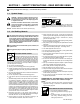
SECTION 1 − SAFETY PRECAUTIONS - READ BEFORE USING som _2007−04 7 Protect yourself and others from injury — read and follow these precautions. 1-1. Symbol Usage DANGER! − Indicates a hazardous situation which, if not avoided, will result in death or serious injury. The possible hazards are shown in the adjoining symbols or explained in the text. Indicates a hazardous situation which, if not avoided, could result in death or serious injury.
FUMES AND GASES can be hazardous. Welding produces fumes and gases. Breathing these fumes and gases can be hazardous to your health. D Keep your head out of the fumes. Do not breathe the fumes. D If inside, ventilate the area and/or use local forced ventilation at the arc to remove welding fumes and gases. D If ventilation is poor, wear an approved air-supplied respirator.
1-3. Additional Symbols For Installation, Operation, And Maintenance FIRE OR EXPLOSION hazard. D Do not install or place unit on, over, or near combustible surfaces. D Do not install unit near flammables. D Do not overload building wiring − be sure power supply system is properly sized, rated, and protected to handle this unit. FALLING UNIT can cause injury. MOVING PARTS can cause injury. D Keep away from moving parts such as fans. D Keep all doors, panels, covers, and guards closed and securely in place.
1-4. California Proposition 65 Warnings Welding or cutting equipment produces fumes or gases which contain chemicals known to the State of California to cause birth defects and, in some cases, cancer. (California Health & Safety Code Section 25249.5 et seq.) Battery posts, terminals and related accessories contain lead and lead compounds, chemicals known to the State of California to cause cancer and birth defects or other reproductive harm. Wash hands after handling.
SECTION 2 − CONSIGNES DE SÉCURITÉ − LIRE AVANT UTILISATION fre_som_2007−04 7 Se protéger et protéger les autres contre le risque de blessure — lire et respecter ces consignes. 2-1. Symboles utilisés DANGER! − Indique une situation dangereuse qui si on l’évite pas peut donner la mort ou des blessures graves. Les dangers possibles sont montrés par les symboles joints ou sont expliqués dans le texte. Indique une situation dangereuse qui si on l’évite pas peut donner la mort ou des blessures graves.
Il reste une TENSION DC NON NÉGLIGEABLE dans les sources de soudage onduleur quand on a coupé l’alimentation. D Arrêter les convertisseurs, débrancher le courant électrique et décharger les condensateurs d’alimentation selon les instructions indiquées dans la partie Entretien avant de toucher les pièces. DES PIÈCES CHAUDES peuvent provoquer des brûlures graves. D Ne pas toucher à mains nues les parties chaudes. D Prévoir une période de refroidissement avant de travailler à l’équipement.
LES ACCUMULATIONS DE GAZ risquent de provoquer des blessures ou même la mort. D Protéger les bouteilles de gaz comprimé d’une chaleur excessive, des chocs mécaniques, des dommages physiques, du laitier, des flammes ouvertes, des étincelles et des arcs. D Fermer l’alimentation du gaz protecteur en cas de non-utilisation. D Veiller toujours à bien aérer les espaces confinés ou se servir d’un respirateur d’adduction d’air homologué.
LES FILS DE SOUDAGE peuvent provoquer des blessures. LE RAYONNEMENT HAUTE FRÉQUENCE (H.F.) risque de provoquer des interférences. D Ne pas appuyer sur la gâchette avant d’en avoir reçu l’instruction. D Ne pas diriger le pistolet vers soi, d’autres personnes ou toute pièce mécanique en engageant le fil de soudage. DES ORGANES MOBILES peuvent provoquer des blessures. D S’abstenir de toucher des organes mobiles tels que des ventilateurs.
2-5. Principales normes de sécurité Safety in Welding, Cutting, and Allied Processes, ANSI Standard Z49.1, de Global Engineering Documents (téléphone : 1-877-413-5184, site Internet : www.global.ihs.com). Recommended Safe Practices for the Preparation for Welding and Cutting of Containers and Piping, American Welding Society Standard AWS F4.1 de Global Engineering Documents (téléphone : 1-877-413-5184, site Internet : www.global.ihs.com).
OM-188 304 Page 10
SECTION 3 − INTRODUCTION 3-1. Specifications Rated Output at 60% Duty Cycle Voltage Range in CV Mode Amperage Range in CC Mode Max. OpenCircuit Voltage 300 A at 32 VDC, 3-Phase 10−35 V 5−400 A 90 VDC RMS Amps Input at Rated Load Output, 60 Hz 3-Phase at NEMA Load Voltages and Class I Rating 225 A at 29 VDC, 1-Phase 230 V 460 V KVA** KW** 30.5 (0.21*) 18.9 (0.10*) 12.2 (0.09*) 11.6 (0.04*) 47.4 (0.34*) 24.5 (0.14*) 11.3 (0.09*) 7.6 (0.
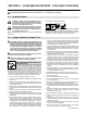
3-3. Volt-Ampere Curves Volt-ampere curves show minimum and maximum voltage and amperage output capabilities of unit. Curves of other settings fall between curves shown.
SECTION 4 − INSTALLATION 4-1. Selecting A Location 24 in (610 mm) Dimensions And Weight 76 lb (34.6 kg) 17 in (432 mm) 12-1/2 in (318 mm) 1 Movement Lifting Handles Use handles to lift unit. ! 1 2 Do not move or operate unit where it could tip. Hand Cart Use cart or similar device to move unit. 3 Rating Label Use rating label to determine input power needs. 1 2 4 Line Disconnect Device Locate unit near correct input power supply.
4-2. Weld Output Receptacles And Selecting Cable Sizes ! ARC WELDING can cause Electromagnetic Interference. To reduce possible interference, keep weld cables as short as possible, close together, and down low, such as on the floor. Locate welding operation 100 meters from any sensitive electronic equipment. Be sure this welding machine is installed and grounded according to this manual.
4-3. Remote 14 Receptacle Information Socket* A B K J 24 VOLTS AC I H C L N D M G E F 115 VOLTS AC REMOTE OUTPUT CONTROL A/V AMPERAGE VOLTAGE GND Socket Information A 24 volts ac. Protected by circuit breaker CB2. B Contact closure to A completes 24 volts ac contactor control circuit. I 115 volts ac. Protected by circuit breaker CB1. J Contact closure to I completes 115 volts ac contactor control circuit. C Output to remote control; +10 volts dc. D Remote control circuit common.
4-5. Electrical Service Guide NOTICE − INCORRECT INPUT POWER can damage this welding power source. This welding power source requires a CONTINUOUS supply of input power at rated frequency(+10%) and voltage (+10%). Phase to ground voltage shall not exceed +10% of rated input voltage. Do not use a generator with automatic idle device (that idles engine when no load is sensed) to supply input power to this welding power source.
4-6. Connecting 1-Phase Input Power 1 8 ! Installation must meet all National and Local Codes − have only qualified persons make this installation. ! Disconnect and lockout/tagout input power before connecting input conductors from unit. ! Always connect green or green/yellow conductor to supply grounding terminal first, and never to a line terminal. =GND/PE Earth Ground 10 . The Auto-Link circuitry in this unit automatically links the power source to the primary voltage being applied.
4-7. Connecting 3-Phase Input Power 3 ! Installation must meet all National and Local Codes − have only qualified persons make this installation. ! Disconnect and lockout/tagout input power before connecting input conductors from unit. ! Always connect green or green/ yellow conductor to supply grounding terminal first, and never to a line terminal. = GND/PE Earth Ground 4 . The Auto-Link circuitry in this unit au- tomatically links the power source to the primary voltage being applied.
SECTION 5 − OPERATION 5-1. Front Panel Controls 1 Power Switch amperage. . The fan motor is thermostatically controlled and only runs when cooling is needed. 2 Voltmeter (see Section 5-2) 3 Ammeter/Trim Indicator (see Section 5-2) 4 Ammeter Light Lights when display beneath is indicating 5 7 Trim Indicator Light Lights when display beneath is indicating trim. 6 Output Adjust Control Controls various output values, depending on mode being used.
5-2. Meter Functions . The meters display the actual weld output values for approximately three seconds after the arc is broken. Mode Meter Reading At Idle V MIG A V 24.5 250 Preset Volts Blank Actual Volts Actual Amps V Trim V A 24.5 250 Blank Pulse Display Actual Volts Actual Amps V A V A Blank Preset Amps Actual Volts Actual Amps V A V A 24.5 Pulsed MIG 50 Stick− Contactor Remote Stick− Contactor ON Manual Pulse 85 80.0 85 24.5 24.
5-3. Example Displays . Values shown are hypothetical. The “A” (Amperage) and “Trim” lights illuminate as shown. Amperage preset display for Stick welding mode. Voltage preset display for MIG welding mode. Display while welding. Preset trim display for Pulse welding mode. Preset pulses per second (PPS) display for Manual Pulse welding mode. . The Stick mode provides the Adaptive Hot Start™ feature, which automatically increases the output amperage at the start of a weld should the start require it.
5-4. Synergic Controls And Overview Controls 1 Display 2 Parameter Select Push Button Press button to move > on display. The parameter indicated by > is selected. 3 3 2 Increment Push Button Press increment button to increase selected parameter. 4 Decrement Push Button Press decrement button decrease selected parameter. to See example at left. Overview The built-in synergic control provides four modes of operation: Manual Pulse MIG − control functions as a discrete pulsed MIG CC control.
5-5. Initial Display, Manual Pulse MIG Mode, MIG Mode, And Stick Mode 1 I N V I S I ON 3 5 4 MP C O P Y R I GH T M I L L E R M f g (C) 2 2 0 0 1 E l e c t r i c Select top line of display, and press Increment or Decrement button until Manual Pulse MIG is displayed. C o . X X X X X X With > on top line, press Increment or Decrement button until Manual Pulse MIG appears. Display scrolls to show line 5.
5-6. Setup Screens To access Setup screens: turn welding power source Off, press and hold Select push button, turn unit On, and hold push button down until initial screen leaves. To exit Setup screens, turn welding power source Off and then On again. Parameters that are displayed when the Setup screens are exited are active.
5-7. Choosing Pulse Programs And Setting Parameters Choosing Pulse Program: Pulse programs are pre-written and cannot be changed by the user. See Section 6 for program parameters and recommended gas mixtures. Choose program depending on the type and size of wire, and type of shielding gas used. For example, the program shown below is for .045 steel wire using Ar/CO2 gas.
5-8.
SECTION 6 − PROGRAMS . Synergic Information: The manufacturer makes no warranties, express or implied, that welds made using the synergic parameters of this equipment will meet the requirements of the application. The synergic parameters contained in this equipment are intended only to be a general guideline. The choice and use of any synergic setting must be tested as to its suitability for the application. 6-1.
Program 2 −− .045 ER70S−3 Mild Steel −− Recommended Gases: Argon/CO2 Gas: Argon/CO2 mixes up to 10% CO2; Argon/O2 mixes up to 5% O2 IPM Trim Peak Amp Background Amp Freq. Pulse Width Starting Amps 80 0 323 48 56 2.20 498 127 10 342 61 91 2.28 529 174 20 370 84 108 2.38 529 221 30 388 95 134 2.53 529 268 40 390 108 155 2.65 529 315 50 400 119 175 2.73 529 362 60 400 139 183 2.83 529 409 70 400 152 200 2.86 529 456 80 400 178 215 2.
Program 5 −− .035 Aluminum 4043 −− Argon IPM Trim Peak Amp Background Amp Freq. Pulse Width Starting Amps 140 0 194 29 60 1.10 400 213 10 196 53 76 1.15 501 286 20 205 80 98 1.20 529 359 30 249 103 109 1.35 529 432 40 272 134 118 1.50 529 505 50 298 150 125 1.70 529 578 60 320 170 135 1.90 529 651 70 340 191 145 2.10 529 724 80 360 214 155 2.25 529 797 90 381 225 165 2.40 529 870 100 400 240 175 2.55 529 Program 6 −− .
Program 8 −− .047 Aluminum 5356 −− Argon IPM Trim Peak Amp Background Amp Freq. Pulse Width Starting Amps 140 0 274 45 50 1.30 529 199 10 280 73 60 1.40 529 258 20 294 95 70 1.60 529 317 30 310 111 95 1.85 529 376 40 323 122 107 2.10 529 435 50 337 141 116 2.30 529 494 60 349 155 129 2.50 529 553 70 359 175 140 2.70 529 612 80 368 192 156 2.90 529 671 90 389 221 166 3.10 529 730 100 400 260 222 3.30 529 Program 9 −− .
Program 11 −− .045 Metal Core −− Recommended Gases: Argon/CO2 Gas: Argon/CO2 mixes up to 20% CO2 IPM Trim Peak Amp Background Amp Freq. Pulse Width Starting Amps 100 0 310 45 50 2.30 529 145 10 330 61 65 2.45 529 190 20 354 70 90 2.55 529 235 30 365 78 110 2.65 529 280 40 370 89 130 2.75 529 325 50 376 100 150 2.85 529 370 60 381 111 165 3.00 529 415 70 385 122 180 3.15 529 460 80 390 138 190 3.25 529 505 90 395 155 200 3.
SECTION 7 − MAINTENANCE & TROUBLESHOOTING 7-1. Routine Maintenance ! . Maintain more often Disconnect power before maintaining. during severe conditions. 3 Months Repair Or Replace Cracked Cables Replace Damaged Or Unreadable Labels Replace Cracked Torch Body Repair Or Replace Cracked Cables And Cords Clean And Tighten Weld Connections 6 Months Blow Out Inside 7-2. Blowing Out Inside Of Unit ! Do not remove case when blowing out inside of unit.
7-3. Voltmeter/Ammeter Help Displays 1 2 3 4 5 V A HE.L P−0 V A HE.L P−1 V A HE.L P−2 V A HE.L P−3 V A HE.L P−4 . All directions are in reference to the front of the unit. All circuitry referred to is located inside the unit. 1 Help 0 Display Indicates a shorted thermistor RT2 on the left side of the unit. If this display is shown, contact a Factory Authorized Service Agent. 2 Help 1 Display Indicates a malfunction in the primary power circuit.
7-4. Error Codes 1 2 Program CRC Error Program Range Error If either error code appears, reset the display to factory settings as follows: 1 Press Parameter Select push button or turn welding power source Off and back On. Change settings and continue. E R R OR P r o g r a m M e m o r y P r e s s C R C W i l l B e R e s e t P a r m. S e l e c t 2 E R R OR P r o g r a m M e m o r y P r e s s R a n g e W i l l B e R e s e t P a r m. S e l e c t 7-5.
Notes Start Your Professional Welding Career Now! 400 Trade Square East, Troy, Ohio 45373 1-800-332-9448 www.welding.
SECTION 8 − ELECTRICAL DIAGRAM 197 556-B Figure 8-1.
206 283-A Figure 8-2.
23 63 62 61 60 OM−188 304 Page 38 59 1 64 58 2 57 65 66 56 68 55 54 3 53 4 5 6 67 7 8 11 10 52 9 49 Figure 9-1. Parts Assembly 50 48 51 12 17 47 46 13 14 15 16 11 44 45 43 18 42 19 24 41 20 40 25 39 23 21 9 26 35 28 36 27 37 not available unless listed. 12 33 34 31 32 29 22 .
Item No. Dia. Mkgs. Part No. Description Quantity Figure 9-1. Parts Assembly . . . 1 . . . . . . . . . . . . . . +175 148 . . . . . . . . . . . . . . . . . . . . . 178 551 . . . . . . . . . . . . . . . . . . . . . 175 256 . . . 2 . . . . . . . . . . . . . . . 195 585 . . . 3 . . . . . . . . . . . . . . . 138 442 . . . 4 . . . . . HD1 . . . . . 182 918 . . . 5 . . . . . . . . . . . . . . . 203 342 . . . 6 . . . . . . . . . . . . . . . 203 341 . . . 7 . . . . . . . . . . . . . . . 181 853 . . . 8 . . . .
Item No. Dia. Mkgs. Part No. Description Quantity Figure 9-1. Parts Assembly (continued) . . . 38 . . . . . PC2 . . . . +212 210 . . Circuit Card Assy, Interconnecting W/Cmpnts (230/460) . . . . . . . . . . . . . 1 . . . 38 . . . . . PC2 . . . . +208 783 . . Circuit Card, Interconnect (460/575) . . . . . . . . . . . . . . . . . . . . . . . . . . . . . . 1 . . . . . . . . . . PLG13 . . . . 131 204 . . Connector & Sockets (RC1) . . . . . . . . . . . . . . . . . . . . . . . . . . . . . . . . . . . . . 1 .
229895 Notes MATERIAL THICKNESS GAUGE
Notes Work like a Pro! Pros weld and cut safely. Read the safety rules at the beginning of this manual.
Effective January 1, 2007 (Equipment with a serial number preface of “LH” or newer) Warranty Questions? Call 1-800-4-A-MILLER for your local Miller distributor. Your distributor also gives you ... Service You always get the fast, reliable response you need. Most replacement parts can be in your hands in 24 hours. Support Need fast answers to the tough welding questions? Contact your distributor. The expertise of the distributor and Miller is there to help you, every step of the way.
Owner’s Record Please complete and retain with your personal records. Model Name Serial/Style Number Purchase Date (Date which equipment was delivered to original customer.) Distributor Address City State Zip For Service Contact a DISTRIBUTOR or SERVICE AGENCY near you. Always provide Model Name and Serial/Style Number. Contact your Distributor for: Welding Supplies and Consumables Options and Accessories Personal Safety Equipment Service and Repair Miller Electric Mfg. Co.