OM-236 948H 2009−06 Processes Stick (SMAW) Welding TIG (GTAW) Welding MIG (GMAW) Welding Flux Cored (FCAW) Welding Air Carbon Arc (CAC-A) Cutting and Gouging Description Engine Driven Welding Generator Big Blue 300 P PRO 300 CAT ® File: Engine Drive Visit our website at www.MillerWelds.
From Miller to You Thank you and congratulations on choosing Miller. Now you can get the job done and get it done right. We know you don’t have time to do it any other way. That’s why when Niels Miller first started building arc welders in 1929, he made sure his products offered long-lasting value and superior quality. Like you, his customers couldn’t afford anything less. Miller products had to be more than the best they could be. They had to be the best you could buy.
TABLE OF CONTENTS SECTION 1 − SAFETY PRECAUTIONS − READ BEFORE USING . . . . . . . . . . . . . . . . . . . . . . . . . . . . . . . . . . 1-1. Symbol Usage . . . . . . . . . . . . . . . . . . . . . . . . . . . . . . . . . . . . . . . . . . . . . . . . . . . . . . . . . . . . . . . . . . . . . . . . 1-2. Arc Welding Hazards . . . . . . . . . . . . . . . . . . . . . . . . . . . . . . . . . . . . . . . . . . . . . . . . . . . . . . . . . . . . . . . . . . 1-3. Engine Hazards . . . . . . . . . . . . . . . . . .
TABLE OF CONTENTS SECTION 8 − MAINTENANCE & TROUBLESHOOTING . . . . . . . . . . . . . . . . . . . . . . . . . . . . . . . . . . . . . . . . . . . 8-1. Routine Maintenance . . . . . . . . . . . . . . . . . . . . . . . . . . . . . . . . . . . . . . . . . . . . . . . . . . . . . . . . . . . . . . . . . . 8-2. Maintenance Label . . . . . . . . . . . . . . . . . . . . . . . . . . . . . . . . . . . . . . . . . . . . . . . . . . . . . . . . . . . . . . . . . . . . 8-3. Servicing Air Cleaner . . . . . . . . . . . .
SECTION 1 − SAFETY PRECAUTIONS − READ BEFORE USING rom_2008−08 Protect yourself and others from injury — read and follow these precautions. 1-1. Symbol Usage DANGER! − Indicates a hazardous situation which, if not avoided, will result in death or serious injury. The possible hazards are shown in the adjoining symbols or explained in the text. Indicates a hazardous situation which, if not avoided, could result in death or serious injury.
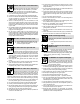
FUMES AND GASES can be hazardous. Welding produces fumes and gases. Breathing these fumes and gases can be hazardous to your health. Keep your head out of the fumes. Do not breathe the fumes. If inside, ventilate the area and/or use local forced ventilation at the arc to remove welding fumes and gases. If ventilation is poor, wear an approved air-supplied respirator.
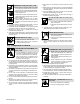
1-3. Engine Hazards BATTERY EXPLOSION can BLIND. Always wear a face shield, rubber gloves, and protective clothing when working on a battery. Stop engine before disconnecting or connecting battery cables or servicing battery. Do not allow tools to cause sparks when working on a battery. Do not use welder to charge batteries or jump start vehicles. Observe correct polarity (+ and −) on batteries. Disconnect negative (−) cable first and connect it last. FUEL can cause fire or explosion.
HYDRAULIC FLUID can injure or kill. Before working on hydraulic system, turn off and lockout/tagout unit, release pressure, and be sure hydraulic pressure cannot be accidentally applied. Relieve pressure before disconnecting or connecting hydraulic lines. Check hydraulic system components and all connections and hoses for damage, leaks, and wear before operating unit.
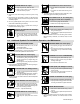
MOVING PARTS can injure. Keep away from fans, belts and rotors. Keep all doors, panels, covers, and guards closed and securely in place. Keep hands, hair, loose clothing, and tools away from moving parts. Before working on compressed air system, turn off and lockout/ tagout unit, release pressure, and be sure air pressure cannot be accidentally applied. Have only qualified people remove guards or covers for maintenance and troubleshooting as necessary.
H.F. RADIATION can cause interference. High-frequency (H.F.) can interfere with radio navigation, safety services, computers, and communications equipment. Have only qualified persons familiar with electronic equipment perform this installation. The user is responsible for having a qualified electrician promptly correct any interference problem resulting from the installation. If notified by the FCC about interference, stop using the equipment at once.
SECTION 2 − CONSIGNES DE SÉCURITÉ − LIRE AVANT UTILISATION rom_2008−08fre Se protéger, ainsi que toute autre personne travaillant sur les lieux, contre les étincelles et le métal chaud. 2-1. Signification des symboles DANGER! − Indique une situation dangereuse qui si on l’évite pas peut donner la mort ou des blessures graves. Les dangers possibles sont montrés par les symboles joints ou sont expliqués dans le texte.
DES PIÈCES CHAUDES peuvent provoquer des brûlures graves. Ne pas toucher à mains nues les parties chaudes. Prévoir une période de refroidissement avant de travailler à l’équipement. Ne pas toucher aux pièces chaudes, utiliser les outils recommandés et porter des gants de soudage et des vêtements épais pour éviter les brûlures. DES PIECES DE METAL ou DES SALETES peuvent provoquer des blessures dans les yeux.
LES CHAMPS MAGNETIQUES peuvent affecter des implants médicaux. Porteur de simulateur cardiaque ou autre implants médicaux, rester à distance. Les porteurs d’implants doivent d’abord consulter leur médecin avant de s’approcher des opérations de soudage à l’arc, de soudage par points, de gougeage, du coupage plasma ou de chauffage par induction. Si des BOUTEILLES sont endommagées, elles pourront exploser. Des bouteilles de gaz protecteur contiennent du gaz sous haute pression.
L’utilisation d’un groupe autonome à l’intérieur PEUT VOUS TUER EN QUELQUES MINUTES. Les fumées d’un groupe autonome contient du monoxyde de carbone. C’est un poison invisible et inodore. JAMAIS utiliser dans une maison ou garage, même avec les portes et fenêtres ouvertes. Uniquement utiliser à l’EXTERIEUR, loin des portes, fenêtres et bouches aération. L’ACIDE DE LA BATTERIE peut provoquer des brûlures dans les YEUX et sur la PEAU. Ne pas renverser la batterie. Remplacer une batterie endommagée.
LIRE LES INSTRUCTIONS. Lire le manuel d’utilisation avant d’installer, d’utiliser ou d’intervenir sur l’appareil. N’utiliser que les pièces de rechange recommandées par le constructeur. Effectuer l’entretien en respectant les manuels d’utilisation, les normes industrielles et les codes nationaux, d’état et locaux. 2-5. Dangers liés à l’air comprimé Un ÉQUIPEMENT PNEUMATIQUE risque de provoquer des blessures ou même la mort.
Le MÉTAL CHAUD provenant du découpage ou du gougeage à l’arc risque de provoquer un incendie ou une explosion. Ne pas découper ou gouger à proximité de produits inflammables. Attention aux risques d’incendie: tenir un extincteur à proximité. LIRE LES INSTRUCTIONS. Lire le manuel d’utilisation avant d’installer, d’utiliser ou d’intervenir sur l’appareil. N’utiliser que les pièces de rechange recommandées par le constructeur.
LE RAYONNEMENT HAUTE FRÉQUENCE (H.F.) risque de provoquer des interférences. Le rayonnement haute fréquence (H.F.) peut provoquer des interférences avec les équipements de radio−navigation et de communication, les services de sécurité et les ordinateurs. Demander seulement à des personnes qualifiées familiarisées avec des équipements électroniques de faire fonctionner l’installation.
2-9. Information EMF Considérations sur le soudage et les effets de basse fréquence et des champs magnétiques et électriques. Le courant de soudage, pendant son passage dans les câbles de soudage, causera des champs électromagnétiques. Il y a eu et il y a encore un certain souci à propos de tels champs.
SECTION 3 − DEFINITIONS 3-1. Warning Label Definitions S-177 571 1 + 2 2 3 + 3 1 4 DIESEL 5 4 6 5 7 0 − 50 h Std. 200A Remove unit from shipping crate. Remove Owner’s Manual from unit. Follow instructions to install muffler. Read Owner’s Manual. Read labels on unit. Use Diesel Fuel only, and fill fuel tank. Leave room for expansion. Warning! Watch Out! There are possible hazards as shown by the symbols. Read Owner’s Manual. Follow instructions to activate battery. Check oil level.
3-2. Symbols And Definitions Some symbols are found only on CE products.
SECTION 4 − SPECIFICATIONS 4-1. Weld, Power, And Engine Specifications Welding Mode Weld Output Range Maximum OpenCircuit Voltage Rated Welding Output Generator Power Rating Engine Fuel Capacity 400 A, 23 Volts DC, 30% Duty Cycle CC/DC 300 A, 32 Volts DC 60% Duty Cycle Stick: 40 − 410 A TIG: 20 − 410 A 250 A, 30 Volts DC 100% Duty cycle 65 400 A, 23 Volts DC, 30% Duty Cycle CV/DC Single-Phase, 10 kVA/kW, 84/42 A, 120/240 V AC, 60 Hz 300 A, 29 Volts DC 60% Duty Cycle 14 − 40 V Catepillar C1.
4-3. Volt-Ampere Curves A. Stick Mode The volt-ampere curves show the minimum and maximum voltage and amperage output capabilities of the welding generator. Curves of all other settings fall between the curves shown. 100 90 80 DC Volts 70 60 50 40 30 Max Min 20 10 0 0 100 200 300 DC Amperes 400 500 600 400 500 600 B. MIG Mode 100 90 80 DC Volts 70 60 50 Max 40 30 20 Min 10 0 0 100 200 300 DC Amperes C.
4-4. Fuel Consumption The curve shows typical fuel use under weld or power loads. 2.00 U.S. GAL/HR. 1.75 1.50 1.25 1.00 0.75 0.50 0.25 0.00 IDLE 0 50 100 150 200 250 300 350 400 DC WELD AMPERES AT 100% DUTY CYCLE 237 471 4-5. Duty Cycle And Overheating 1 1 100% Duty Cycle Duty Cycle is percentage of 10 minutes that unit can weld at rated load without overheating. This unit is rated for welding at 250 amperes continuously. NOTICE − Exceeding duty cycle can damage unit and void warranty.
4-6. AC Generator Power Curve The ac power curve shows the generator power in amperes available at the 120 and 240 volt receptacles. 150 300 AC VOLTS 125 250 100 200 75 150 50 100 25 50 0 0 0 20 40 60 80 AC AMPERES IN 240 V MODE 0 40 80 120 160 AC AMPERES IN 120 V MODE 237 494 Notes MATERIAL THICKNESS REFERENCE CHART 24 Gauge (.025 in) 22 Gauge (.031 in) 20 Gauge (.037 in) 18 Gauge (.050 in) 16 Gauge (.063 in) 14 Gauge (.078 in) 1/8 in (.125 in) 3/16 in (.188 in) 1/4 in (.
SECTION 5 − INSTALLATION 5-1. Serial Number And Rating Label Location The serial number and rating information for this product is located on the front. Use rating label to determine input power requirements and/or rated output. For future reference, write serial number in space provided on back cover of this manual. 5-2. Installing Welding Generator Movement ! Do not move or operate unit where it could tip.
5-3. Mounting Welding Generator ! Supporting The Unit Do not weld on base. Welding on base can cause fuel tank fire or explosion. Weld only on the four mounting brackets or bolt unit down. NOTICE − Do not mount unit by supporting the base only at the four mounting brackets. Use crosssupports to adequately support unit and prevent damage to base. 2 Mounting Surface: 1 2 OR Cross-Supports Mounting Brackets (Supplied) Mount unit on flat surface or use cross-supports to support base.
5-4. Grounding Generator To Truck Or Trailer Frame 1 ! Always ground generator frame to vehicle frame to prevent electric shock and static electricity hazards. ! Also see AWS Safety & Health Fact Sheet No. 29, Grounding of Portable And Vehicle Mounted Welding Generators. ! Bed liners, shipping skids, and some running gear insulate the welding generator from the vehicle frame. Always connect a ground wire from the generator equipment grounding terminal to bare metal on the vehicle frame as shown.
5-5. Installing Exhaust Pipe ! Stop engine and let cool. Point exhaust pipe in desired di- rection but always away from front panel and direction of travel. Tools Needed: 1/2 in. 803 582 / Ref. 217 357-A Notes Work like a Pro! Pros weld and cut safely. Read the safety rules at the beginning of this manual.
5-6. Activating The Dry Charge Battery (If Applicable) ! 3 Always wear a face shield, rubber gloves and protective clothing when working on a battery. Remove battery from unit. 1 2 2 1 3 Vent Caps Sulfuric Acid Electrolyte (1.265 Specific Gravity) Well Fill each cell with electrolyte to bottom of well (maximum). ! Do not overfill battery cells. Wait ten minutes and check electrolyte level. If necessary, add electrolyte to raise to proper level. Reinstall vent caps.
5-8. Engine Prestart Checks Check radiator coolant level when fluid is low in recovery tank. Full Full Diesel Capacity: 6 qt (5.7 L) Coolant Recovery Tank Hot Full Cold Full Full 803 563 Check all engine fluids daily. Engine stops if fuel level is low. Engine must be cold and on a level surface. Unit is shipped with 20W break-in oil. Automatic shutdown system stops engine if oil pressure is too low or coolant temperature is too high. Oil This unit has a low oil pressure shut- down switch.
5-9. Connecting To Weld Output Terminals Stick and TIG Welding For Stick and TIG welding Direct Current Electrode Positive (DCEP), connect electrode holder cable to CC (Stick/TIG) terminal on right and work cable to Work/Negative (−) terminal on left. For Direct Current Electrode Negative (DCEN), reverse cable connections. Use Process/Contactor switch to select type of weld output (see Section 6-3). ! Stop engine.
5-10. Selecting Weld Cable Sizes* Weld Cable Size** and Total Cable (Copper) Length in Weld Circuit Not Exceeding*** Weld Output Terminals ! Stop engine before connecting to weld output terminals. ! Do not use worn, damaged, undersized, or poorly spliced cables.
5-11. Connecting To Remote 14 Receptacle RC14 Socket* A 24 volts ac. Protected by supplementary protector CB8. B Contact closure to A completes 24 volt ac contactor control circuit. C Output to remote control:+10 volts dc in MIG mode; 0 to +10 volts dc in Stick or TIG mode. D Remote control circuit common. E DC input command signal: 0 to +10 volts from min. to max. of remote control with Voltage/ Amperage Adjust control at max.
SECTION 6 − OPERATING WELDING GENERATOR 6-1.
6-2. Description Of Front Panel Controls (See Section 6-1) Engine Starting Controls Engine Gauges, Meters, And Lights 1 See Section 6-6 for complete fuel/hour Preheat Switch In Run position, engine runs at weld/power speed. In Run/Idle position (optional), engine runs at idle speed at no load and weld speed with load applied. gauge information. 4 Fuel/Hour Gauge Use gauge to check fuel level, total engine operating hours, or hours to oil change.
6-3. Process/Contactor Switch 1 1 Process/Contactor Switch ! Weld output terminals are energized when Process/Contactor switch is in a Weld Terminals Always On position and the engine is running. Use switch to select weld process and weld output on/off control (see table below). Place switch in Remote On/Off Switch Required positions to turn weld output on and off with a device connected to the Remote 14 receptacle.
6-4. Lift-Arct TIG With Crater-Out And Auto-Stopt Arc Start With Lift-Arc TIG Lift-Arc is used for the DCEN GTAW process when HF Start method is not permitted. Select Lift-Arc at Process/Contactor switch. Arc Start With Lift-Arc 1 Turn gas on. 1 2 2 Touch or scratch. Lift at any angle. Touch tungsten electrode to workpiece at weld start point. Slowly lift electrode. Arc is started when electrode is lifted.
6-5. Remote Voltage/Amperage Control 1 Remote 14 Receptacle RC14 Connect optional remote control to RC14 (see Section 5-11). When a remote control is connected to the Remote receptacle, the Auto Sense Remote feature automatically switches voltage/amperage control to the remote control. When a device is connected to the Remote receptacle, remote voltage/amperage control is always available regardless of the position of the Process/Contactor switch.
6-6.
SECTION 7 − OPERATING AUXILIARY EQUIPMENT 7-1. Generator Power Receptacles 1 3 2 4 5 6 217 357-A 1 120 V 20 A AC (shown) Receptacle RC5 and/or GFCI1 2 120 V 20 A AC GFCI (shown) Receptacle RC6 and/or GFCI2 3 240 V 50 A AC Receptacle RC11 RC5 / 6 and GFCI1 / 2 supply 60 Hz singlephase power at weld/power speed. Receptacle configuration varies depending on machine model and serial number. Maximum output from these receptacles is 2.4 kVA/kW.
SECTION 8 − MAINTENANCE & TROUBLESHOOTING 8-1. Routine Maintenance ! Recycle engine fluids. = Check = Change = Clean * To be done by Factory Authorized Service Agent Stop engine before maintaining. See Engine Manual and Maintenance Label for important start-up, service, and storage information. Service engine more often if used in severe conditions.
8-2.
8-3. Servicing Air Cleaner ! 1 2 3 Stop engine. NOTICE − Do not run engine without air cleaner or with dirty element. Engine damage caused by using a damaged element is not covered by the warranty. 4 The air cleaner primary element can be cleaned but the dirt holding capacity of the filter is reduced with each cleaning. The chance of dirt reaching the clean side of the filter while cleaning and the possibility of filter damage makes cleaning a risk.
8-4. Inspecting And Cleaning Optional Spark Arrestor Muffler Tools Needed: 3/8 in. ! Stop engine and let cool. 1 Spark Arrestor Muffler 2 Cleanout Plug Remove plug and remove any dirt covering cleanout hole. 3 Exhaust Pipe Start engine and run at idle speed to blow out cleanout hole. If nothing blows out of hole, briefly cover end of exhaust pipe with fireproof material. ! 3 Stop engine and let cool. Reinstall cleanout plug. 1 2 803 582 / Ref. 214 778-B 8-5.
8-6. Adjusting Engine Speed On Standard Models ! Engine Speed (No Load) RPM (Hz) Weld/Power 1880 (61.7) Maximum Stop engine and let cool. Engine speed is factory set and should not require adjustment. After tuning engine, check engine speed with tachometer or frequency meter. See table for proper no load speed. If necessary, adjust speed as follows: Start engine and run until warm. Turn Process/Contactor switch to Weld Terminals Always On − Stick position. 1 Lock Nut 2 Adjustment Screw 3 Loosen nut.
8-7. Adjusting Engine Speed On Models With Automatic Idle (Optional) Engine Speed (No Load) 1880 rpm max (62.6 Hz) 1500 rpm (50 Hz) Engine Speed Adjustment After tuning engine, check engine speed with tachometer or frequency meter. See table for proper no load speed. If necessary, adjust speed as follows: Start engine and run until warm. Turn Process/Contactor switch to Stick − Weld Terminals Always On position.
8-8. Servicing Fuel And Lubrication Systems ! Stop engine and let cool. ! After servicing, start engine and check for fuel leaks. Stop engine, tighten connections as necessary, and wipe up spilled fuel. 1 2 3 Oil Filter Oil Drain Valve And Hose Oil Fill Cap 4 Primary (Canister) Fuel Filter 5 Secondary (In-Line) Fuel Filter 6 Fuel Tank Sludge Drain Valve To change oil and filter: Route oil drain hose and valve through hole in base.
8-9. Overload Protection ! Stop engine. When a circuit breaker, supplementary protector, or fuse opens, it usually indicates a more serious problem exists. Contact Factory Authorized Service Agent. 1 Fuse F1 F1 protects the stator exciter winding from overload. If F1 opens, weld and generator power is low or stops entirely.
8-10. Checking Generator Brushes ! Stop engine and let cool. 1 Generator Brush With Spring Mark and disconnect leads at brush holder cap. Remove brushes. Replace brushes if damaged or if brush material is at or near minimum length. 5/16 in. (8 mm) Minimum Length 9/16 in. (14.3 mm) New Length Replace Damaged Brushes 1 Ref 2114 778−D / S−0233−A Notes MATERIAL THICKNESS REFERENCE CHART 24 Gauge (.025 in) 22 Gauge (.031 in) 20 Gauge (.037 in) 18 Gauge (.050 in) 16 Gauge (.063 in) 14 Gauge (.
8-11. Voltmeter/Ammeter Help Displays Use the Voltmeter/Ammeter help displays to diagnose and correct fault conditions. When a help code is displayed normally weld output has stopped but generator power output may be okay. To 1 HL.P 20 HL.P 21 2 reset help displays, stop unit and then restart. See item 6 below to reset Help 25 display. 1 2 3 HL.P 22 4 23 HL.P 25 5 Help 21 Display Indicates thermistor TH1 on the main rectifier heat sink has failed.
8-12. Troubleshooting Also see Voltmeter/Ammeter help displays to assist in troubleshooting weld problems (see Section 8-11). A. Welding Trouble Remedy No weld output; generator power output Place Process/Contactor switch in a Weld Terminals Always On position, or place switch in a Remote okay at ac receptacles. On/Off Switch Required position and turn remote contactor on (see Section 5-11). Reset supplementary protector CB7 or CB8 (see Section 8-9). Check for faulty remote device connected to RC14.
B. Generator Power Trouble Remedy No generator power output at ac recep- Reset receptacle supplementary protector(s) (see Section 7-1). tacles; weld output okay. No generator power or weld output. Disconnect equipment from generator power receptacles during start-up. Check fuse F1, and replace if open (see Section 8-9). Have Factory Authorized Service Agent check field excitation circuit. Reset supplementary protector CB3 (see Section 8-9). Check Voltmeter/Ammeter help displays (see Section 8-11).
Trouble Engine slowly stopped and cannot be restarted. Remedy Check fuel level. Check fuel/hour gauge for indication of shutdown. Check engine air and fuel filters (see Sections 8-3 and 8-8). See engine manual. Battery discharges between uses. Turn Engine Control switch off when unit is not running. Clean top of battery with baking soda and water solution; rinse with clear water. Recharge or replace battery if necessary. Periodically recharge battery (approximately every 3 months).
SECTION 9 − ELECTRICAL DIAGRAMS Figure 9-1.
240 670-A OM-236 948 Page 51
SECTION 10 − RUN-IN PROCEDURE run_in1 2007−04 10-1. Wetstacking NOTICE − Do not perform run-in procedure at less than 20 volts weld output and do not exceed duty cycle or equipment damage may occur. 1 2 1 Welding Generator Run diesel engines near rated voltage and current during run-in period to properly seat piston rings and prevent wetstacking. See nameplate, rating label, or specifications section in this manual to find rated voltage and current. NOTICE − Do not idle engine longer than necessary.
10-2. Run-In Procedure Using Load Bank 4 2 1 ! Stop engine. ! Do not touch hot exhaust pipe, engine parts, or load bank/grid. ! Keep exhaust and pipe away from flammables. NOTICE − Do not perform run-in procedure at less than 20 volts weld output and do not exceed duty cycle or equipment damage may occur. 1 Load Bank Turn all load bank switches Off. If needed, connect load bank to 115 volts ac wall receptacle or generator auxiliary power receptacle.
10-3. Run-In Procedure Using Resistance Grid 6 2 ! Stop engine. ! Do not touch hot exhaust pipe, engine parts, or load bank/grid. ! Keep exhaust and pipe away from flammables. NOTICE − Do not perform run-in procedure at less than 20 volts weld output and do not exceed duty cycle or equipment damage may occur. 1 1 Resistance Grid Use grid sized for generator rated output. Turn Off grid.
SECTION 11 − GENERATOR POWER GUIDELINES The views in this section are intended to be representative of all engine-driven welding generators. Your unit may differ from those shown. 11-1. Selecting Equipment 1 2 3 1 Generator Power Receptacles − Neutral Bonded To Frame 3-Prong Plug From Case Grounded Equipment 2-Prong Plug From Double Insulated Equipment Be sure equipment has double insulated symbol and/or wording on it. 2 ! Do not use 2-prong plug unless equipment is double insulated.
11-3. Grounding When Supplying Building Systems 1 1 2 2 GND/PE Equipment Grounding Terminal Grounding Cable Use #10 AWG or larger insulated copper wire. 3 Ground Device Use ground device as stated in electrical codes. 2 ! Ground generator to system earth ground if supplying power to a premises (home, shop, farm) wiring system. ! Also see AWS Safety & Health Fact Sheet No. 29, Grounding of Portable And Vehicle Mounted Welding Generators. 3 ST-800 576-B 11-4.
11-5.
11-7. Approximate Power Requirements For Contractor Equipment Contractor Hand Drill Circular Saw Table Saw Band Saw Bench Grinder Air Compressor Electric Chain Saw Electric Trimmer Electric Cultivator Elec.
11-8. Power Required To Start Motor Single-Phase Induction Motor Starting Requirements Motor Start Code G H J K L M N P KVA/HP 6.3 7.1 8.0 9.0 10.0 11.2 12.5 14.0 4 1 3 AC MOTOR VOLTS 230 AMPS 2.5 CODE M Hz 60 HP 1/4 PHASE 1 1 2 3 4 2 Motor Start Code Running Amperage Motor HP Motor Voltage To find starting amperage: Step 1: Find code and use table to find kVA/HP. If code is not listed, multiply running amperage by six to find starting amperage. Step 2: Find Motor HP and Volts.
11-10. Typical Connections To Supply Standby Power 1 2 Utility Electrical Service Have only qualified persons perform these connections according to all applicable codes and safety practices. ! Properly install and ground this equipment according to its Owner’s Manual and national, state, and local codes.
11-11. Selecting Extension Cord (Use Shortest Cord Possible) Cord Lengths for 120 Volt Loads If unit does not have GFCI receptacles, use GFCI-protected extension cord.
SECTION 12 − PARTS LIST Hardware is common and not available unless listed. Wirng harnesses are listed at the end of parts section. 6 7 15 8 16 17 18 9 10 19 11 5 14 112 26 20 21 22 12 13 23 24 25 4 (Fig.12-5) 3 2 1 101 102 111 110 (Fig.12-3) 103 109 97 98 96 95 94 93 92 100 99 108 (Fig.12-2) 104 106 105 107 Figure 12-1.
33 32 30 29 34 44 31 37 36 39 27 78 38 77 75 76 45 73 74 47 70 88 72 68 67 66 89 86 85 69 71 80(Fig.
Item No. Dia. Mkgs. Part No. Description Quantity Figure 12-1. Main Assembly . . . 1 . . . . HD1 . . . . 168829 . . Transducer, Current 1000a Module Max Open Loop . . . . . . . . . . . . . . . . . . . . 2 . . . . . R3 . . . . . 213027 . . Resistor, WW Tap 300 W 40 Ohm . . . . . . . . . . . . . . . . . . . . . . . . . . . . . . . . . . . . 3 . . . . . . . . . . . . . . 217070 . . Bracket, Rectifier . . . . . . . . . . . . . . . . . . . . . . . . . . . . . . . . . . . . . . . . . . . . . . . . . . 4 . .
Item No. Dia. Mkgs. Part No. Description Quantity Figure 12-1. Main Assembly (Continued) . . . 46 . . . . . . . . . . . . . . 190190 . . Tank, Coolant Recovery . . . . . . . . . . . . . . . . . . . . . . . . . . . . . . . . . . . . . . . . . 1 . . . 47 . . . . . . . . . . . . . . 213502 . . Guard, Fan . . . . . . . . . . . . . . . . . . . . . . . . . . . . . . . . . . . . . . . . . . . . . . . . . . . . 1 . . . 48 . . . . . . . . . . . . . . 237382 . . Label, Diesel Engine Maintenance Cat C1.5 . . . .
Item No. Dia. Mkgs. Part No. Description Quantity Figure 12-1. Main Assembly (Continued) . . . 83 . . . . . . . . . . . . . . 212623 . . Tank, Fuel (Includes Fuel Cap And Items Below) . . . . . . . . . . . . . . . . . . . . 1 . . . 84 . . . . . . . . . . . . . . 189908 . . . . Valve, Drain Fuel 180 Deg Zinc Pld . . . . . . . . . . . . . . . . . . . . . . . . . . . . . . 1 . . . 85 . . . . . . . . . . . . . . 181572 . . . . Bushing, Tank Fuel . . . . . . . . . . . . . . . . . . . . . . . . . . . . . . .
Hardware is common and not available unless listed. Wirng harnesses are listed at the end of parts section. 11 10 12 8 9 13 7 14 15 6 5 16 4 1 2 23 17 3 18 19 37 36 24 25 24 26 22 27 20 21 35 28 29 30 31 34 32 33 803 684-D Figure 12-2. Panel, Front w/Components Item No. Dia. Mkgs. Part No. Description Quantity Figure 12-2. Panel, Front w/Components (Figure 12-1 Item 108) ... ... ... ... ... ... ... ... ... 1 2 3 4 5 6 7 8 9 . . . . . . . . . . . . . . 097926 . . . . . .
Item No. Dia. Mkgs. Part No. Description Quantity Figure 12-2. Panel, Front w/Components (Continued) . . . 10 . . . . . . . . . . . . . . 214543 . . . . . 11 . . . . . . . . . . . . . . 134201 . . . . . 12 . . . . PC2 . . . . 214660 . . . . . 13 . . . . . R1 . . . . . 214760 . . . . . 14 . . . . . R2 . . . . . 193118 . . . . . 15 . . . . . S4 . . . . . 021467 . . . . . 16 . . . . . S1 . . . . . 217680 . . . . . . . . . . . . . . . . . . . . . . 207073 . . . . . . . . . . . . . . . . . . . . . .
5 Hardware is common and not available unless listed. 4 Wirng harnesses are listed at 3 the end of parts section. 2 6 7 1 8 9 10 12 11 13 803 689-E 14 Figure 12-3. Control Panel Item No. Dia. Mkgs. Part No. Description Quantity Figure 12-3. Control Panel (Figure 12-1 Item 110) ... ... ... ... ... ... ... ... ... ... ... ... ... ... 1 2 3 4 5 6 7 8 9 10 11 12 13 14 . . . . . . . . . . . . . . 220981 . . . . . . . . . . . . . . 129524 . . . . CR2 . . . . 214876 . . . . CB1 . . . . 190374 .
5 Hardware is common and not available unless listed. 4 Wirng harnesses are listed at the end of parts section. 6 7 3 1 2 9 8 10 11 12 13 14 20 19 18 17 16 15 803 686-B Figure 12-4. Generator Item No. Dia. Mkgs. Part No. Description Quantity Figure 12-4. Generator (Figure 12-1 Item 80) ... ... ... ... ... ... ... ... ... ... ... ... ... ... ... ... ... ... ... ... 1 2 3 4 5 6 7 8 9 10 11 12 13 14 15 16 17 18 19 20 . . . ROTOR . . . .............. .............. .............. .......
Hardware is common and not 6 available unless listed. 1 Wirng harnesses are listed at the end of parts section. 3 2 7 10 8 5 4 9 803 685-A Figure 12-5. Rectifier Assembly Item No. Dia. Mkgs. Part No. Description Quantity Figure 12-5. Rectifier Assembly (Figure 12-1 Item 4) .................... ... 1 .............. . . . 2 . . MOD1,2,3 . . . . . 3 . . MOD4,5,6 . . ... 4 .............. ... 5 .............. ... 6 .............. . . . 7 . . . . TH1 . . . . . . . 8 . . . . C1−6 . . . . . . . 9 . .
Some wiring harness components (switches, relays, supplementary protectors) are also referenced elsewhere in this parts list. Purchase components separately or as part of the associated wiring harness. Item No. Dia. Mkgs. Part No. Description Quantity Wiring Harnesses .................... . . . . . . . . . . . S4 . . . . . . . . . . SR1, SR2, SR3 . . . . . . . . . . CB1 . . . . . . . . . . . . CB2, CB3 . . . . . . . . . . . . CR3 . . . . . . . . . . . . . . CR2 . . . . .................... .........
Effective January 1, 2009 (Equipment with a serial number preface of LK or newer) Warranty Questions? Call 1-800-4-A-MILLER for your local Miller distributor. Your distributor also gives you ... Service You always get the fast, reliable response you need. Most replacement parts can be in your hands in 24 hours. Support Need fast answers to the tough welding questions? Contact your distributor. The expertise of the distributor and Miller is there to help you, every step of the way.
Owner’s Record Please complete and retain with your personal records. Model Name Serial/Style Number Purchase Date (Date which equipment was delivered to original customer.) Distributor Address City State Zip For Service Contact a DISTRIBUTOR or SERVICE AGENCY near you. Always provide Model Name and Serial/Style Number. Contact your Distributor for: Welding Supplies and Consumables Options and Accessories Personal Safety Equipment Service and Repair Miller Electric Mfg. Co.