
Owner`s manual


OM-236 948 Page 46
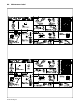
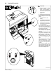
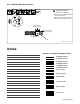
8-11. Voltmeter/Ammeter Help Displays
Use the Voltmeter/Ammeter help
displays to diagnose and correct
fault conditions.
When a help code is displayed
normally weld output has
stopped but generator power
output may be okay.
To reset help displays, stop
unit and then restart. See item
6 below to reset Help 25 dis-
play.
1 Help 20 Display
Indicates a failure of meter display
module PC2, or the wiring between
PC2 and main control module PC1.
If this display is shown, have Facto-
ry Authorized Service Agent check
PC1, PC2, and the wiring between
PC1 and PC2.
2 Help 21 Display
Indicates thermistor TH1 on the
main rectifier heat sink has failed.
If this display is shown, have Facto-
ry Authorized Service Agent check
TH1, and the wiring between TH1
and PC1.
3 Help 22 Display
Indicates the rectifier heat sink has
overheated. If this display is shown,
check generator cooling system
and/or reduce duty cycle. Keep en-
gine access door closed when run-
ning to maintain proper cooling air
flow past rectifier. Allow unit to cool
before restarting. If problem contin-
ues, have Factory Authorized Ser-
vice Agent check unit.
4 Help 23 Display
Can indicate a complete loss of
generator excitation, auxiliary pow-
er output, and weld output or a fail-
ure of one of the rectifier output
SRCs. If generator output is lost,
see trouble “No generator power or
weld output.” in section 8-12B. If
generator output is okay, have Fac-
tory Authorized Service Agent
check the rectifier SCRs.
5 Help 25 Display
Indicates a remote device con-
nected to Remote Receptacle
RC14 may be faulty. Help 25 is also
displayed whenever a remote de-
vice has been connected to RC14
and then disconnected. Clear fault
by stopping and restarting the unit
or by turning Process/Contactor
switch to another position. If prob-
lem continues, have Factory Autho-
rized Service Agent check the re-
mote device, filter board PC6, and
main control module PC1.
2
1
HL.P
22
HL.P
23
HL.P
25
HL.P
20
HL.P
21
5
4
3
803 562 / 217 357-A