OM-4421 215 075N 2007−01 Processes Stick (SMAW) Welding TIG (GTAW) Welding MIG (GMAW) Welding Flux Cored (FCAW) Welding Air Carbon Arc (CAC-A) Cutting and Gouging Description Engine Driven Welding Generator Big Blue 400P Big Blue 500 X (Perkins-Powered) File: Engine Drive Visit our website at www.MillerWelds.
From Miller to You Thank you and congratulations on choosing Miller. Now you can get the job done and get it done right. We know you don’t have time to do it any other way. That’s why when Niels Miller first started building arc welders in 1929, he made sure his products offered long-lasting value and superior quality. Like you, his customers couldn’t afford anything less. Miller products had to be more than the best they could be. They had to be the best you could buy.
TABLE OF CONTENTS SECTION 1 − SAFETY PRECAUTIONS − READ BEFORE USING . . . . . . . . . . . . . . . . . . . . . . . . . . . . . . . . . . 1-1. Symbol Usage . . . . . . . . . . . . . . . . . . . . . . . . . . . . . . . . . . . . . . . . . . . . . . . . . . . . . . . . . . . . . . . . . . . . . . . . 1-2. Arc Welding Hazards . . . . . . . . . . . . . . . . . . . . . . . . . . . . . . . . . . . . . . . . . . . . . . . . . . . . . . . . . . . . . . . . . . 1-3. Engine Hazards . . . . . . . . . . . . . . . . . .
TABLE OF CONTENTS SECTION 7 − OPERATING WELDING GENERATOR − CC/CV MODELS . . . . . . . . . . . . . . . . . . . . . . . . . . . . . 7-1. Front Panel Controls For CC/CV Models (See Section 7-2) . . . . . . . . . . . . . . . . . . . . . . . . . . . . . . . . . . 7-2. Description Of Front Panel Controls For CC/CV Models (See Section 7-1) . . . . . . . . . . . . . . . . . . . . . . 7-3. Process/Contactor Switch On CC/CV Models . . . . . . . . . . . . . . . . . . . . . . . . . . . . . . . . . . . . . . . . . . .
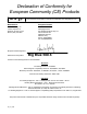
Declaration of Conformity for European Community (CE) Products NOTE This information is provided for units with CE certification (see rating label on unit). Manufacturer: European Contact: Miller Electric Mg. Co. 1635 W. Spencer St. Appleton, WI 54914 USA Phone: (920) 734-9821 Mr. Danilo Fedolfi, Managing Director ITW Welding Products Italy S.r.l.
Declaration of Conformity for European Community (CE) Products NOTE This information is provided for units with CE certification (see rating label on unit). Manufacturer: European Contact: Notified Body: Miller Electric Mg. Co. 1635 W. Spencer St. Appleton, WI 54914 USA Phone: (920) 734-9821 Mr. Danilo Fedolfi, Managing Director ITW Welding Products Italy S.r.l.
SECTION 1 − SAFETY PRECAUTIONS − READ BEFORE USING rom _nd_3/05 Warning: Protect yourself and others from injury — read and follow these precautions. 1-1. Symbol Usage Means Warning! Watch Out! There are possible hazards with this procedure! The possible hazards are shown in the adjoining symbols. Marks a special safety message. Means “Note”; not safety related. This group of symbols means Warning! Watch Out! possible ELECTRIC SHOCK, MOVING PARTS, and HOT PARTS hazards.
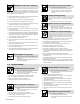
WELDING can cause fire or explosion. HOT PARTS can cause severe burns. Welding on closed containers, such as tanks, drums, or pipes, can cause them to blow up. Sparks can fly off from the welding arc. The flying sparks, hot workpiece, and hot equipment can cause fires and burns. Accidental contact of electrode to metal objects can cause sparks, explosion, overheating, or fire. Check and be sure the area is safe before doing any welding. Remove all flammables within 35 ft (10.
STEAM AND HOT COOLANT can burn. If possible, check coolant level when engine is cold to avoid scalding. Always check coolant level at overflow tank, if present on unit, instead of radiator (unless told otherwise in maintenance section or engine manual). If the engine is warm, checking is needed, and there is no overflow tank, follow the next two statements. Wear safety glasses and gloves and put a rag over radiator cap.
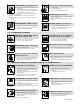
READ INSTRUCTIONS. Use only genuine MILLER/Hobart replacement parts. Perform engine and air compressor (if applicable) maintenance and service according to this manual and the engine/air compressor (if applicable) manuals. H.F. RADIATION can cause interference. ARC WELDING can cause interference. High-frequency (H.F.) can interfere with radio navigation, safety services, computers, and communications equipment.
SECTION 2 − CONSIGNES DE SÉCURITÉ − LIRE AVANT UTILISATION rom_fre 3/05 Avertissement: Protégez vous et les autres des blessures − lisez et suivez ces précautions. 2-1. Signification des symboles Signifie Mise en garde ! Soyez vigilant ! Cette procédure présente des risques de danger ! Ceux-ci sont identifiés par des symboles adjacents aux directives. Identifie un message de sécurité particulier. Signifie NOTA ; n’est pas relatif à la sécurité.
LE SOUDAGE peut provoquer un incendie ou une explosion. Le soudage effectué sur des conteneurs fermés tels que des réservoirs, tambours ou des conduites peut provoquer leur éclatement. Des étincelles peuvent être projetées de l’arc de soudure. La projection d’étincelles, des pièces chaudes et des équipements chauds peut provoquer des incendies et des brûlures. Le contact accidentel de l’électrode avec des objets métalliques peut provoquer des étincelles, une explosion, un surchauffement ou un incendie.
Si le moteur est chaud et que le liquide doit être vérifié, opérer comme suivant. Mettre des lunettes de sécurité et des gants, placer un torchon sur le bouchon du radiateur. Dévisser le bouchon légèrement et laisser la vapeur s’échapper avant d’enlever le bouchon. LES ACCUMULATIONS DE GAZ risquent de provoquer des blessures ou même la mort. LA CHALEUR DU MOTEUR peut provoquer un incendie. LES ÉTINCELLES À L’ÉCHAPPEMENT peuvent provoquer un incendie.
LIRE LES INSTRUCTIONS. LE SOUDAGE À L’ARC risque de provoquer des interférences. Utiliser seulement les pièces de rechange d’origine. Effectuer la maintenance du moteur et du compresseur (si applicable) suivant ce manuel et le manuel du moteur/ compresseur (si applicable). LE RAYONNEMENT HAUTE FRÉQUENCE (H.F.) risque de provoquer des interférences. Le rayonnement haute fréquence (H.F.
SECTION 3 − DEFINITIONS 3-1. Warning Label Definitions (For Wordless Labels) S-177 571 1 + 2 2 3 + 3 1 4 DIESEL 5 4 6 5 7 0 − 50 h Std. 200A Remove unit from shipping crate. Remove Owner’s Manual from unit. Follow instructions to install muffler. Read Owner’s Manual. Read labels on unit. Use Diesel Fuel only, and fill fuel tank. Leave room for expansion. Warning! Watch Out! There are possible hazards as shown by the symbols. Read Owner’s Manual. Follow instructions to activate battery.
3-2.
3-3. Symbols And Definitions NOTE A Some symbols are found only on export products.
SECTION 4 − SPECIFICATIONS 4-1.
4-3. Volt-Ampere Curves For CC Models The volt-ampere curve shows the minimum and maximum voltage and amperage output capabilities of the welding generator. Curves of all other settings fall between the curves shown. 100 Ranges: 230 − Max 170 − 365 110 − 225 70 − 130 55 − 85 DC VOLTS 80 60 40 20 0 0 100 200 300 400 500 600 700 800 900 1000 DC AMPERES 215 081-A Notes Work like a Pro! Pros weld and cut safely. Read the safety rules at the beginning of this manual.
4-4. Volt-Ampere Curves For CC/CV Models A. Stick Mode 100 RANGES: MAX 155 − 450 115 − 320 75 − 195 40 − 90 80 DC VOLTS The volt-ampere curves show the minimum and maximum voltage and amperage output capabilities of the welding generator. Curves of all other settings fall between the curves shown. 60 40 20 0 0 100 200 300 400 500 600 DC AMPERES 700 800 900 1000 400 700 800 900 1000 B. MIG Mode 100 80 DC VOLTS 60 MAX 40 20 MIN 0 0 100 200 300 500 600 DC AMPERES C.
4-5. Fuel Consumption The curve shows typical fuel use under weld or power loads. 2.50 2.25 2.00 US Gal./Hr. 1.75 1.50 1.25 1.00 0.75 0.50 IDLE 0.25 0.00 0 50 100 150 200 250 300 350 400 450 DC WELD AMPERES AT 100% DUTY CYCLE 500 199 032−A 4-6. Duty Cycle And Overheating 100% Duty Cycle At 400 Amperes Duty Cycle is percentage of 10 minutes that unit can weld at rated load without overheating. Exceeding duty cycle can damage unit and void warranty.
4-7. AC Generator Power Curve The ac power curve shows the generator power in amperes available at the 120 and 240 volt receptacles. 150 300 AC VOLTS 125 250 100 200 75 150 50 100 25 50 0 0 0 5 10 15 20 AC AMPERES IN 240V MODE 10 20 30 40 AC AMPERES IN 120V MODE 0 25 30 50 60 193 018 4-8. Optional Three-Phase Generator Curves A.
SECTION 5 − INSTALLATION 5-1. Installing Welding Generator Always securely fasten welding generator onto transport vehicle or trailer and comply with all DOT and other applicable codes. Movement Always ground generator frame to vehicle frame to prevent electric shock and static electricity hazards. OR If unit does not have GFCI receptacles, use GFCI-protected extension cord. OR Do not install unit where air flow is restricted or engine may overheat. See Section 4-2 for lifting eye rating.
5-2. Using Lifting Eye 1 2 3 1 Lifting Eye Nut Carriage Bolt Raise lifting eye until it snaps in place. Lower lifting eye when not needed. 2 To lock the lifting eye in the upright position, insert a 3/8-16 x 1-1/2 in carriage bolt through slot in bracket and secure with nut (bolt and nut not supplied). Tools Needed: 3 Ref. 802 311 Notes Work like a Pro! Pros weld and cut safely. Read the safety rules at the beginning of this manual.
5-3. Mounting Welding Generator Do not weld on base. Welding on base can cause fuel tank fire or explosion. Weld only on the four mounting brackets or bolt unit down. Supporting The Unit Do not mount unit by supporting the base only at the four mounting brackets. Use cross-supports to adequately support unit and prevent damage to base. 2 Mounting Surface: 1 2 OR Cross-Supports Mounting Brackets (Supplied) Mount unit on flat surface or use cross-supports to support base.
5-4. Installing Exhaust Pipe Stop engine and let cool. Point exhaust pipe in desired di- rection but always away from front panel and direction of travel. Tools Needed: 1/2 in Ref. 803 604 / Ref. 215 158 Notes Work like a Pro! Pros weld and cut safely. Read the safety rules at the beginning of this manual.
5-5. Activating The Dry Charge Battery (If Applicable) Always wear a face shield, rubber gloves and protective clothing when working on a battery. 3 Remove battery from unit. 5 6 2 7 1 Vent Caps Sulfuric Acid Electrolyte (1.265 Specific Gravity) Well Fill each cell with electrolyte to bottom of well (maximum). Do not overfill battery cells. Wait ten minutes and check electrolyte level. If necessary, add electrolyte to raise to proper level. Reinstall vent caps.
5-7. Engine Prestart Checks Check radiator coolant level when fluid is low in recovery tank. Full Capacity: 404.22 Engine: 9.5 qt (9.01L) Full Diesel Full Coolant Recovery Tank Hot Full Cold Full 803 603 Check all engine fluids daily. Engine must be cold and on a level surface. Unit is shipped with 20W break-in oil. Automatic shutdown system stops engine if oil pressure is too low or coolant temperature is too high. This unit has a low oil pressure shut- down switch.
5-8. Connecting To Weld Output Terminals Stick and TIG Welding For Stick and TIG welding Direct Current Electrode Positive (DCEP), connect electrode holder cable to Positive (+) terminal on left and work cable to Negative (−) terminal on right. For Direct Current Electrode Negative (DCEN), reverse cable connections. If equipped with optional Polarity switch or optional Polarity/AC switch, connect electrode holder cable to Electrode (+) terminal on left and work cable to Work (−) terminal on right.
5-9. Selecting Weld Cable Sizes* Weld Cable Size** and Total Cable (Copper) Length in Weld Circuit Not Exceeding*** 100 ft (30 m) or Less 150 ft (45 m) 200 ft (60 m) 250 ft (70 m) 300 ft (90 m) 350 ft 400 ft (105 m) (120 m) Weld Output Terminals Stop engine before connecting to weld output terminals.
5-11. Connecting To Remote 14 Receptacle RC14 On CC/CV Models Socket* A 24 volts ac. Protected by supplementary protector CB5. B Contact closure to A completes 24 volt ac contactor control circuit. C Output to remote control:+10 volts dc in MIG or Stick mode; 0 to +10 volts dc in TIG mode. D Remote control circuit common. E DC input command signal: 0 to +10 volts from min. to max. of remote control with Voltage/ Amperage Adjust control at max.
SECTION 6 − OPERATING WELDING GENERATOR − CC MODELS 6-1.
6-2. Description Of Front Panel Controls For CC Models (See Section 6-1) Engine Starting Controls 6 1 Starting Aid Switch Use switch to energize starting aid for cold weather starting (see starting instructions following). Normal temperature is 180 - 203° F (82 - 95° C). Engine stops if temperature exceeds 220° F (104° C). 2 7 Engine Control Switch Use switch to start and stop engine. To Start: Do not use ether. Using ether voids warranty.
6-3. Remote Amperage Control On CC Models (Optional) 1 Remote Amperage Adjust Receptacle RC13 Connect optional remote control to RC13 (see Section 5-10). 1 In Example: Range = 110 to 225 A DC Percentage Of Range = 50% Max = About 168 A DC (50% of 110 to 225) Example: Combination Remote Amperage Control (Stick) Max (168 A DC) Min (90 A DC) Set Switches Set Range Set Control Adjust Optional Remote Control Ref. 154 862-A / Ref. 181 711-A / 803 602 6-4.
Notes OM-4421 Page 29
SECTION 7 − OPERATING WELDING GENERATOR − CC/CV MODELS 7-1.
7-2. Description Of Front Panel Controls For CC/CV Models (See Section 7-1) Engine Starting Controls 1 Starting Aid Switch Use switch to energize starting aid for cold weather starting (see starting instructions following). 2 Engine Control Switch Use gauge to check battery voltage and monitor the engine charging system. The meter should read about 14 volts dc when the engine is running, and about 12 volts dc when the engine is stopped.
7-3. Process/Contactor Switch On CC/CV Models 1 Process/Contactor Switch Weld output terminals are energized when Process/Contactor switch is in an Weld Terminals Always On position and the engine is running. 1 DC voltage is still present at the weld terminals when Process/ Contactor switch is in the Remote On/Off Switch Required − Stick position and the engine is running. Use switch to select weld process and weld output on/off control (see table below and Section 7-4).
7-4. Remote Voltage/Amperage Control On CC/CV Models (Optional) 1 Remote 14 Receptacle RC14 Connect optional remote control to RC14 (see Section 5-11).
SECTION 8 − OPERATING AUXILIARY EQUIPMENT 8-1. 120 Volt And 240 Volt Receptacles 1 120 V 20 A AC GFCI Receptacle GFCI1 2 240 V 30 A AC Twistlock Receptacle RC1 Receptacles supply 60 Hz singlephase power at weld/power speed. 1 3 2 If a ground fault is detected, GFCI Reset button pops out and receptacle does not work. Check for faulty tools plugged in receptacle. Press button to reset GFCI1.
8-2. Connecting To Optional Three-Phase Generator (CC/CV Models Only) Place Process/Contactor switch 1 Single-Phase Power Connection in Weld Terminals Always On Stick position when using threephase generator (see Section 7-3). 2 Single-Phase Generator Power 1 120/240 V 50 A Receptacle RC5 RC5 is connected to the optional three-phase generator and supplies 60 Hz single-phase power at weld/ power speed. Maximum output from RC5 is 12 kVA/kW. Power available at RC5 is reduced when welding.
8-3. Optional Generator Power Receptacles European Receptacle 5 1 2 6 1 120 V 20 A AC GFCI Receptacle GFCI1 2 240 V 16 A AC European Receptacle RC1 3 240 V 15 A AC Australian Receptacle RC1 4 240 V 15 A AC South African Receptacle RC1 Receptacles supply 60 Hz singlephase power at weld/power speed. If a ground fault is detected, the GFCI Reset button pops out and the receptacle does not work. Check for faulty tools plugged in receptacle. Press button to reset GFCI1.
SECTION 9 − MAINTENANCE & TROUBLESHOOTING 9-1.
9-2. Routine Maintenance Stop engine before maintaining. See Engine Manual and Maintenance Label Recycle engine for important start-up, service, and storage fluids. information. Service engine more often if used in severe conditions.
9-3. Checking Generator Brushes Stop engine and let cool. 1 Generator Brush Mark and disconnect leads at brush holder cap. Remove brushes. Replace brushes if damaged or if brush material is at or near minimum length. Minimum Length: 5/8 in (16 mm) New Length: 1-1/4 in (32 mm) Replace Damaged Brushes 1 Ref 215 158 Notes Work like a Pro! Pros weld and cut safely. Read the safety rules at the beginning of this manual.
9-4. Servicing Air Cleaner Stop engine. 1 2 3 Do not run engine without air cleaner or with dirty element. Engine damage caused by using a damaged element is not covered by the warranty. 4 The air cleaner primary element can be cleaned but the dirt holding capacity of the filter is reduced with each cleaning. The chance of dirt reaching the clean side of the filter while cleaning and the possibility of filter damage makes cleaning a risk.
9-5. Inspecting And Cleaning Optional Spark Arrestor Muffler Stop engine and let cool. 1 Spark Arrestor Muffler 2 Cleanout Plug Remove plug and remove any dirt covering cleanout hole. 2 Start engine and run at idle speed to blow out cleanout hole. If nothing blows out of hole, briefly cover end of exhaust pipe with fireproof material. Stop engine and let cool. Reinstall cleanout plug. 1 Tools Needed: 3/8 in 803 656 / Ref.
9-6. Adjusting Engine Speed Engine Speed (No Load) 1850 rpm max (61.6 Hz) 1250 rpm (41.6 Hz) After tuning engine, check engine speed with tachometer or frequency meter. See table for proper no load speed. Start engine and run until warm. On CC models, place Stick/TIG switch in Stick position. On CC/CV models, turn Process/ Contactor switch to Stick − Weld Terminals Always On position. 1 Low Speed Adjustment Screw 2 Lock Nut Standard Model Idle Speed Adjustment Loosen lock nut.
9-7. Servicing Fuel And Lubrication Systems Stop engine and let cool. After servicing, start engine and check for fuel leaks. Stop engine, tighten connections as necessary, and wipe up spilled fuel. 4 5 3 6 7 1 2 3 Oil Filter Oil Drain Valve And Hose Oil Fill Cap 4 Fuel Line 5 Primary Fuel Filter (Fuel/ Water Separator) 6 Petcock 7 Secondary Fuel Filter 8 Fuel Tank Sludge Drain Valve To change oil and filter: 1 Route oil drain hose and valve through hole in base.
9-8. Overload Protection Stop engine. When a supplementary protector, circuit breaker or fuse opens, it usually indicates a more serious problem exists. Contact Factory Authorized Service Agent. 1 2 2 F1 and F2 protect the stator exciter winding from overload. If F1 opens, weld and generator power is low or stops entirely. If F2 opens, weld output is low or stops entirely. 4 kVA/kW generator power is still available.
9-9. Troubleshooting A. Welding − CC Models Trouble Remedy No weld output; generator power output Check position of Ampere Range switch. okay at ac receptacles. Check position of optional Polarity switch. Place Amperage Adjust switch in Panel position, or place switch in Remote position and connect remote control to Remote Amperage Adjust receptacle RC13 (see Sections 5-10 and 6-1). Check and secure connections to Remote Amperage Adjust receptacle RC13 (see Section 5-10).
Trouble No remote fine amperage control. Remedy Repair or replace remote control device. Have Factory Authorized Service Agent check OCV control circuit. B. Welding − CC/CV Models Trouble Remedy No weld output; generator power output Place Process/Contactor switch in a Weld Terminals Always On position, or place switch in a Remote okay at ac receptacles. On/Off Switch Required position and connect remote contactor to optional Remote 14 receptacle RC14 (see Sections 5-11 and 7-1).
Trouble Remedy No remote fine amperage or voltage Repair or replace remote control device. control. Have Factory Authorized Service Agent check PC1 sensing leads (36 and 37), and connections. Constant speed wire feeder does not Reset supplementary protector CB5 or CB6 (see Section 9-8). work. Check and secure connections to Remote 14 receptacle RC14 (see Section 5-11). Repair or replace wire feeder. Low CV weld output. Set Ampere Range switch to highest range.
E. Engine Trouble Engine will not crank. Remedy Check battery, and replace if necessary. Check battery connections and tighten if necessary. Circuit breaker CB10 may be open. CB10 automatically resets when fault is corrected (see Section 9-8). Have Factory Authorized Service Agent check engine wiring harness and components. Check engine wiring harness plug connections. Have Factory Authorized Service Agent check control relay CR1 and Engine Control switch S1. Engine cranks but does not start.
Notes OM-4421 Page 49
SECTION 10 − ELECTRICAL DIAGRAMS Figure 10-1.
223 522-B OM-4421 Page 51
Figure 10-2.
223 523-B OM-4421 Page 53
SECTION 11 − RUN-IN PROCEDURE run_in1 11/05 11-1. Wetstacking Do not perform run-in procedure at less than 20 volts weld output and do not exceed duty cycle or equipment damage may occur. 1 2 Welding Generator Run diesel engines near rated voltage and current during run-in period to properly seat piston rings and prevent wetstacking. See nameplate, rating label, or specifications section in this manual to find rated voltage and current. Do not idle engine longer than necessary.
11-2. Run-In Procedure Using Load Bank Stop engine. Do not touch hot exhaust pipe, engine parts, or load bank/grid. Keep exhaust and pipe away from flammables. 4 2 1 Do not perform run-in procedure at less than 20 volts weld output and do not exceed duty cycle or equipment damage may occur. 1 Load Bank Turn all load bank switches Off. If needed, connect load bank to 115 volts ac wall receptacle or generator auxiliary power receptacle.
11-3. Run-In Procedure Using Resistance Grid Stop engine. Do not touch hot exhaust pipe, engine parts, or load bank/grid. Keep exhaust and pipe away from flammables. 6 Do not perform run-in procedure at less than 20 volts weld output and do not exceed duty cycle or equipment damage may occur. 2 1 Resistance Grid Use grid sized for generator rated output. 1 Turn Off grid.
SECTION 12 − GENERATOR POWER GUIDELINES NOTE The views in this section are intended to be representative of all engine-driven welding generators. Your unit may differ from those shown. 12-1. Selecting Equipment 1 2 3 Generator Power Receptacles − Neutral Bonded To Frame 3-Prong Plug From Case Grounded Equipment 2-Prong Plug From Double Insulated Equipment Do not use 2-prong plug unless equipment is double insulated. 1 2 3 Be sure equipment has this symbol and/or wording. OR gen_pwr 11/02 − Ref.
12-3. Grounding When Supplying Building Systems 1 1 2 Equipment Grounding Terminal Grounding Cable 2 GND/PE Use #10 AWG or larger insulated copper wire. 3 Ground Device Ground generator to system earth ground if supplying power to a premises (home, shop, farm) wiring system. 2 Use ground device as stated in electrical codes. 3 ST-800 576-B 12-4. How Much Power Does Equipment Require? 1 3 2 1 VOLTS 115 AMPS 4.
12-5.
12-7. Approximate Power Requirements For Contractor Equipment Contractor Hand Drill Circular Saw Table Saw Band Saw Bench Grinder Air Compressor Electric Chain Saw Electric Trimmer Electric Cultivator Elec.
12-8. Power Required To Start Motor 4 1 3 AC MOTOR VOLTS 230 AMPS 2.5 CODE M Hz 60 HP 1/4 PHASE 1 1 2 3 4 2 Motor Start Code Running Amperage Motor HP Motor Voltage To find starting amperage: Step 1: Find code and use table to find kVA/HP. If code is not listed, multiply running amperage by six to find starting amperage. Step 2: Find Motor HP and Volts. Step 3: Determine starting amperage (see example). Welding generator amperage output must be at least twice the motor’s running amperage.
12-10. Typical Connections To Supply Standby Power Properly install and ground this equipment according to its Owner’s Manual and national, state, and local codes. 1 2 Utility Electrical Service 3 Transfer Switch 4 Fused Disconnect Switch (If Required) Welding Generator Output 5 Essential Loads Have only qualified persons perform these connections according to all applicable codes and safety practices. Switch transfers the electrical load from electric utility service to the generator.
12-11. Selecting Extension Cord (Use Shortest Cord Possible) Cord Lengths for 120 Volt Loads If unit does not have GFCI receptacles, use GFCI-protected extension cord.
SECTION 13 − PARTS LIST 127 Hardware is common and not available unless listed. 400 P Models Only 24 23 22 6 7 19 8 2 3 5 4 20 21 25 27 18 9 10 11 12 1 26 13 17 14 15 16 28 29 31 112 32 111 110 30 109 118 (CV) 119 (CV) 120 126 117 Fig. 13−7 121 122 113 114 (Fig. 13-2 OR 13-3 115 123 116 (CC ONLY) 124 125 (Fig. 13-4 OR 13-5) Figure 13-1.
39 35 37 36 40 38 54 53 52 34 33 51 55 50 41 56 48 47 42 57 49 43 45 58 44 59 46 61 93 (Fig.
Item No. Dia. Mkgs. Part No. Description Quantity Figure 13-1. Main Assembly . . . 1 . . . . . . . . . . . . . 189 824 . . . 1 . . . . . . . . . . . . ♦199 294 . . . 2 . . . . . . . . . . . . . 191 626 . . . 3 . . . . . . . . . . . . . 189 975 . . . 4 . . . . . . . . . . . . +200 989 . . . 4 . . . . . . . . . . . ♦+210 736 . . . 5 . . . . . . . . . . . . . 199 592 . . . 6 . . . . . . . . . . . . . 190 076 . . . 6 . . . . . . . . . . . . ♦202 635 . . . 7 . . . . . . . . . . . . . 190 992 . . . 8 . . . .
Item No. Dia. Mkgs. Part No. Description Quantity Figure 13-1. Main Assembly (Continued) . . . 40 . . . . . . . . . . . . ♦202 629 . . COVER, radiator access ss . . . . . . . . . . . . . . . . . . . . . . . . . . . . . . . . . . . . . . . . . . 41 . . . . . . . . . . . . . 191 354 . . SUPPORT, cover . . . . . . . . . . . . . . . . . . . . . . . . . . . . . . . . . . . . . . . . . . . . . . . . . . . 41 . . . . . . . . . . . . ♦202 633 . . SUPPORT, cover e−coat . . . . . . . . . . . . . . . . . . . . .
Item No. Dia. Mkgs. Part No. Description Quantity Figure 13-1. Main Assembly (Continued) . . . 77 . . . . . . . . . . . . . 191 626 . . BUMPER, door engine access . . . . . . . . . . . . . . . . . . . . . . . . . . . . . . . . . . . . . . . 78 . . . . . . . . . . . . . 199 592 . . LATCH, paddle series 20 (black) . . . . . . . . . . . . . . . . . . . . . . . . . . . . . . . . . . . . . 79 . . . . . . . . . . . . . 220 539 . . LABEL, diesel engine maintenance . . . . . . . . . . . . . . . . . . . . . . .
Item No. Dia. Mkgs. Part No. Description Quantity Figure 13-1. Main Assembly (Continued) . . 120 . . . . . . . . . . . ♦199 305 . . TOP, cover front upright ss . . . . . . . . . . . . . . . . . . . . . . . . . . . . . . . . . . . . . . . 1 . . 121 . . . . . . . . . . . . 212 944 . . LABEL, cc stick overlap weld ranges . . . . . . . . . . . . . . . . . . . . . . . . . . . . . . . 1 . . 122 . . . . . . . . . . . . . . . . . . . . . . . Not Applicable . . . . . . . . . . . . . . . . . . . . . . . . . . .
Hardware is common and not available unless listed. 7 6 8 9 5 10 4 11 3 12 13 2 1 15 16 14 17 24 23 18 19 21 20 22 803 647-F Figure 13-2. Control Box Assembly − CC Models Item No. Dia. Mkgs. Part No. Description Quantity Figure 13-2. Control Box Assembly − CC Models (Figure 13-1 Item 114) ... ... ... ... ... ... ... ... ... ... ... ... ... ... ... ... ... ... ... 1 2 3 4 5 6 7 8 9 10 11 12 13 14 15 16 17 18 19 . . . F1, F2 . . *085 874 . . . . . . . . . . . . . 046 432 . . . . CR7 .
Item No. Dia. Mkgs. Part No. Description Quantity Figure 13-2. Control Box Assembly − CC Models Continued . . . 20 . . . . . . . . . . . . . 201 079 . . . 21 . . . . . C9 . . . . . 087 110 . . . 22 . . . . . . . . . . . . . 177 136 . . . 23 . . . D1/C1 . . 189 701 . . . 24 CB11, 12, 13 139 266 ♦Optional .. .. .. .. .. COVER, control box . . . . . . . . . . . . . . . . . . . . . . . . . . . . . . . . . . . . . . . . . . . . . CAPACITOR, elctlt 240uf 200VDC . . . . . . . . . . . . . . . . . . . . . . .
4 5 6 7 3 8 10 9 2 11 1 12 13 15 16 23 22 18 14 17 19 20 21 803 648-F Figure 13-3. Control Box Assembly − CC/CV Models Item No. Dia. Mkgs. Part No. Description Quantity Figure 13-3. Control Box Assembly − CC/CV Models (Figure 13-1 Item 114) ... ... ... ... ... ... ... ... ... ... ... ... ... ... ... ... ... ... ... 1 2 3 4 5 6 7 8 9 10 11 12 13 14 15 16 17 18 19 . . . F1, F2 . . *085 874 . . . . . . . . . . . . . 046 432 . . . . . . . . . . . . . 201 077 . . . . . . . . . . . . .
Item No. Dia. Mkgs. Part No. Description Quantity Figure 13-3. Control Box Assembly − CC/CV Models (Continued) . . . 20 . . . . . . . . . . . . . . . . 21 . . . D1/C1 . . . . . 22 . . . . TD1 . . . . . . 23 CB11, 12, 13 ♦Optional 177 136 189 701 214 928 139 266 .. .. .. .. CLAMP, capacitor 1.375dia . . . . . . . . . . . . . . . . . . . . . . . . . . . . . . . . . . . . . . . DIODE/CAPACITOR BOARD . . . . . . . . . . . . . . . . . . . . . . . . . . . . . . . . . . . . .
Hardware is common and not available unless listed. 4 3 5 2 1 6 7 8 9 11 10 42 41 40 39 12 13 14 35 38 16 31 30 37 36 34 15 17 32 33 28 29 18 19 21 20 22 27 803 649 26 25 24 Figure 13-4.
Item No. Dia. Mkgs. Part No. Description Quantity Figure 13-4. Panel, Front w/Components − CC Models (Figure 13-1 Item 125) . . . 1 . . . . . . . . . . . . . 215 070 . . .............................. ... 2 ........................ . . . 3 . . . . . . . . . . . . . 215 014 . . . . . 3 . . . . . . . . . . . . ♦220 544 . . . . . 4 . . . . . S3 . . . . 208 278 . . . . . 5 . . . . . R1 . . . . 188 635 . . . . . 6 . . . . . . . . . . . . . 202 209 . . . . . 7 . . . . . S6 . . . . . 011 622 . . . . . 8 . . .
Item No. Dia. Mkgs. Part No. Description Quantity Figure 13-4. Panel, Front w/Components − CC Models (Continued) . . . . . . . . . . . . . . . . . . . 197 798 . . SENDER, Coolant Temp 300 Deg F M16 X 1.5 . . . . . . . . . . . . . . . . . . . . . . 1 . . . 37 . . . . . . . . . . . . . 217 083 . . GAUGE, Pressure Oil 0−100 Psi Electric . . . . . . . . . . . . . . . . . . . . . . . . . . . 1 . . . . . . . . . . . . . . . . . . . 193 230 . . SENDER, Pressure Oil 0− 100 Psi . . . . . . . . . . . . . . . . .
Item No. Dia. Mkgs. Part No. Description Quantity Figure 13-5. Panel, Front w/Components − CC/CV Models (Figure 13-1 Item 125) . . . 1 . . . . . . . . . . . . . 215 158 . . .............................. ... 2 ........................ . . . 3 . . . . . . . . . . . . . 215 014 . . . . . 3 . . . . . . . . . . . . ♦220 544 . . . . . 4 . . . . . S3 . . . . 208 278 . . . . . 5 . . . . . R1 . . . . . 193 118 . . . . . 6 . . . . . S6 . . . . 193 234 . . . . . . . . . . . . . . . . . . . . . . 197527 . . . . .
Item No. Dia. Mkgs. Part No. Description Quantity Figure 13-5. Panel, Front w/Components − CC/CV Models (Continued) . . . 38 . . . . . . . . . . . . . 134 201 . . . 39 . . . . . . . . . . . . . 181 169 . . . 40 . . . . . . . . . . . . . 186 621 . . . 41 . . . . . . . . . . . . ♦059 773 . . . 42 . . . . . . . . . . . . ♦010 647 . . . 43 . . . . . . . . . . . . . 039 047 . . . 44 . . . . . . . . . . . . ♦196 073 . . . 45 . . . . . . . . . . . . . 021 385 . . . 46 . . . . . . . . . . . . . 190 323 . . .
Hardware is common and 20 not available unless listed. 16 11 17 18 15 12 21 10 9 13 14 19 8 22 23 7 6 5 3 1 2 24 4 27 33 36 35 32 30 29 31 26 25 28 34 802 552-B Figure 13-6. Generator Item No. Dia. Mkgs. Part No. Description Quantity Figure 13-6. Generator (Figure 13-1 Item 93) . . . 1 . . . . . . . . . . . . . 132 053 . . SCREW, .375−16x1.50 hex hd−pln gr5 pld . . . . . . . . . . . . . . . . . . . . . . . . . . . . 2 . . . . . . . . . . . . . 183 387 . .
Item No. Dia. Mkgs. Part No. Description Quantity Figure 13-6. Generator (Continued) . . . 21 . . . . . . . . . . . . . 197 486 . . . 22 . . . . . . . . . . . . . 083 883 . . . 23 . . . . . . . . . . . . . 049 026 . . . 24 . . . . . . . . . . . . . 191 579 . . . . . . . . . . . . . . . . . . . 195 560 . . . 25 . . . . . . . . . . . . . 083 883 . . . 26 . . . . . . . . . . . . . 172 555 . . . 27 . . . . . . . . . . . . . 602 159 . . . 28 . . . . . . . . . . . . . 601 961 . . . 29 . . . . . . . . . . . .
Hardware is common and 4 not available unless listed. 3 2 1 5 6 7 8 9 802 279-A Figure 13-7. Main Rectifier Assembly Item No. Dia. Mkgs. Part No. Description Quantity Figure 13-7. Main Rectifier Assembly (Figure 13-1 Item 117) . . . . . . . . . . SR3 . . . ... 1 ............. ... 2 ............. ... 3 ............. ... 4 ............. . . . 5 . . . . PC3 . . . ... 6 ............. ... 7 ............. . . . 8 . D3, D5, D7 . . . 9 .
Note Item No. Some wiring harness components (switches, relays, circuit breakers) are also referenced elsewhere in this parts list. Purchase components separately or as part of the associated wiring harness. Dia. Mkgs. Part No. Description Quantity Wiring Harnesses .................... . . . . . . . . SR1, SR2 . . . . . . . . . . . D1/C1 . . . . . . . . . . . . . RC4 . . . . CB11, CB12, CB13 . . . . . . . . . . . . CR7 . . . . .................... . . . . . . . . . . . S6 . . . . . . . . . . . . . . .
Item No. Dia. Mkgs. Part No. Description Quantity Wiring Harnesses (Continued) .................... D10/C10, D11/C11 . . . . . . . . . . . . . CB10 . . . . . . . . . . . . . . CR1 . . . . .................... . . . . . . . . . . PLG4 . . . . .................... .................... . . . . . . . . . . CR8 . . . . 221376 189701 190374 090104 148850 114062 212116 212117 197325 .. .. .. .. .. .. .. .. .. Harness, engine control (includes) . . . . . . . . . . . . . . . . . . . . . . . . . . . . . .
Effective January 1, 2007 (Equipment with a serial number preface of “LH” or newer) Warranty Questions? Call 1-800-4-A-MILLER for your local Miller distributor. Your distributor also gives you ... Service You always get the fast, reliable response you need. Most replacement parts can be in your hands in 24 hours. Support Need fast answers to the tough welding questions? Contact your distributor. The expertise of the distributor and Miller is there to help you, every step of the way.
Owner’s Record Please complete and retain with your personal records. Model Name Serial/Style Number Purchase Date (Date which equipment was delivered to original customer.) Distributor Address City State Zip For Service Contact a DISTRIBUTOR or SERVICE AGENCY near you. Always provide Model Name and Serial/Style Number. Contact your Distributor for: Welding Supplies and Consumables Options and Accessories Personal Safety Equipment Service and Repair Miller Electric Mfg. Co.