OM-166 941C July 1999 Processes Stick (SMAW) Welding Flux Cored (FCAW) Welding Air Carbon Arc (CAC-A) Cutting and Gouging Description Engine Driven Welding Generator CBI 801D (Per NSPR 10202)
Warranty Effective January 1, 1999 (Equipment with a serial number preface of “KK” or newer) This limited warranty supersedes all previous manufacturers warranties and is exclusive with no other guarantees or warranties expressed or implied. LIMITED WARRANTY − Subject to the terms and conditions below, warrants to its original retail purchaser that new equipment sold after the effective date of this limited warranty is free of defects in material and workmanship at the time it is shipped from factory.
OM-166 941C − 7/99 TABLE OF CONTENTS Section No. Page No. SECTION 1 − SAFETY RULES FOR OPERATION OF ARC WELDING POWER SOURCE 1-1. 1-2. 1-3. 1-4. Introduction . . . . . . . . . . . . . . . . . . . . . . . . . . . . . . . . . . . . . . . . . . . . . . . . General Precautions . . . . . . . . . . . . . . . . . . . . . . . . . . . . . . . . . . . . . . . . . Arc Welding . . . . . . . . . . . . . . . . . . . . . . . . . . . . . . . . . . . . . . . . . . . . . . . . Standards Booklet Index . . . . . . . . . .
SECTION 7-1. 7-2. 7-3. 7-4. 7-5. 7-6. 7-7. 7 − SEQUENCE OF OPERATION Shielded Metal Arc Welding (SMAW) . . . . . . . . . . . . . . . . . . . . . . . . . . Gas Metal Arc (GMAW) And Flux Cored Arc Welding (FCAW) . . . . Air Carbon Arc Cutting And Gouging (CAC-A) . . . . . . . . . . . . . . . . . . . Auxiliary Power Operation . . . . . . . . . . . . . . . . . . . . . . . . . . . . . . . . . . . . Air Compressor Operation . . . . . . . . . . . . . . . . . . . . . . . . . . . . . . . . . . . .
SECTION 1 − SAFETY RULES FOR OPERATION OF ARC WELDING POWER SOURCE 1-1. INTRODUCTION We learn by experience. Learning safety through personal experience, like a child touching a hot stove is harmful, wasteful, and unwise. Let the experience of others teach you. Safe practices developed from experience in the use of welding and cutting are described in this manual. Research, development, and field experience have evolved reliable equipment and safe installation, operation, and servicing practices.
atmosphere or where the radiant energy can penetrate to atmospheres containing even minute amounts of trichloroethylene or perchloroethylene. C. Fire and Explosion Prevention Causes of fire and explosion are: combustibles reached by the arc, flame, flying sparks, hot slag or heated material; misuse of compressed gases and cylinders; and short circuits.
Locate or secure cylinders so they cannot be knocked over. outlet away from people and sources of ignition. Wipe with a clean lintless cloth. Passageways and work areas. Keep cylinders clear of areas where they may be struck. Match regulator to cylinder. Before connecting, check that the regulator label and cylinder marking area, and that the regulator inlet and cylinder outlet match. NEVER CONNECT a regulator designed for a particular gas or gases to a cylinder containing any other gas.
1-3. ARC WELDING Comply with precautions in 1-1, 1-2, and this section. Arc Welding, properly done, is a safe process, but a careless operator invites trouble. The equipment carries high currents at significant voltages. The arc is very bright and hot. Sparks fly, fumes rise, ultraviolet and infrared energy radiates, weldments are hot, and compressed gases may be used. The wise operator avoids unnecessary risks and protects himself and others from accidents.
quate to carry ground currents safely. Equipment made electrically HOT by stray current may shock, possibly fatally. Do NOT GROUND to electrical conduit, or to a pipe carrying ANY gas or flammable liquid such as oil or fuel. ject in contact with the electrode circuit unless the welding power source is off. b.
5. ANSI Standard Z41.1, STANDARD FOR MEN’S SAFETY-TOE FOOTWEAR obtainable from the American National Standards Institute, 1430 Broadway, New York, NY 10018. 6. ANSI Standard Z49.2, FIRE PREVENTION IN THE USE OF CUTTING AND WELDING PROCESSES obtainable from the American National Standards Institute, 1430 Broadway, New York, NY 10018. 7. 8. AWS Standard A6.0, WELDING AND CUTTING CONTAINERS WHICH HAVE HELD COMBUSTIBLES obtainable from the American Welding Society, 550 N.W. LeJeune Rd, Miami, FL 33126.
SECTION 3 − SPECIFICATIONS Table 3-1. Welding Generator Specifications Rated Output At 100% Duty Cycle Welding Range Maximum Open-Circuit Voltage (OCV) 800 Amperes 100 to 800 At 36 Volts DC Amps DC Maximum Engine Speed (No Load) Single-Phase Auxiliary Power While Welding 1860 RPM 3 kVA/kW 60 Hz 26 Amperes At 120 Volts 95 Volts DC 80 Volts DC Nominal Weight Net Ship 2150 lbs. 2280 lbs. (975 kg) (1034 kg) Conforms with NEMA EW1 (ANSI C87.1), “ELECTRIC ARC WELDING POWER SOURCES,” Class I (100).
3-1. DUTY CYCLE The duty cycle of a welding generator is the percentage of a ten minute period that a welding generator can be operated at a given output without causing overheating and damage to the unit. This welding generator is rated at 100 percent duty cycle when operated at 800 amperes. This means that the welding generator can be operated at 800 amperes continuously without causing damage to the unit. 3-2.
A. Lifting Of Equipment WARNING: INCORRECT LIFTING will damage internal parts; FALLING EQUIPMENT can cause serious personal injury and equipment damage. • Use lifting eye to lift unit only, NOT gas cylinders, trailer, or any other heavy options, accessories, or devices. • Use equipment of adequate capacity to lift the unit. • Use lift forks at least 42 in. (1067 mm) long. • Lift only from engine-end (end opposite front panel). B.
4-4. FUEL WARNING: REMOVE FUEL CAP SLOWLY; FUEL SPRAY may cause injury; FUEL may be under pressure. • Rotate fuel cap slowly and wait until hissing stops before removing cap. ENGINE FUEL can cause fire or explosion. • Stop engine before checking or adding fuel. • Do not spill fuel; if spilled, wipe up. • Do not refuel if engine is hot or running. • Do not refuel near sparks or open flame. • Do not smoke while refueling. • Do not fill fuel tank to top; allow 1/2 in.
4-7. WELD OUTPUT CONNECTIONS (Table 4-1 And Figure 4-2) B. Weld Cable Preparation 1. Install electrode holder to cable following manufacturer’s instructions. Always use an insulated electrode holder to ensure operator safety. 2. Install correct size lugs onto ends of both cables for connecting to work clamp, electrode holder or wire feeder, and weld output terminals. 3. Install work clamp onto cable.
2. For Shielded Metal Arc Welding (SMAW) and Air Carbon Arc Cutting and Gouging (CAC-A) (Electrode Positive/Reverse Polarity), connect weld cables as follows: 4-8. REMOTE CONTROL CONNECTIONS A. Remote 9 Receptacle Information Connections (Figures 4-2 And 4-3) And REMOTE 9 a. Connect one end of work cable to NEGATIVE (−) weld output terminal. FEEDER b. Connect end of electrode holder cable to POSITIVE (+) weld output terminal.
If supplied remote control cord is not suitable for connecting to the REMOTE 9 receptacle RC3, proceed with one of the following alternatives; 1. 2. G I B. REMOTE Terminal Strip 3T Information And Connections (Figures 4-2 And 4-4) WARNING: ELECTRIC SHOCK can kill; UNEXPECTED OUTPUT can cause serious injury. • Do not touch live electrical parts. • Stop engine, and disconnect negative (−) battery cable from battery before making any internal inspection or connections.
4-9. AIR COMPRESSOR CONNECTIONS This unit delivers 12 cfm of air at a pressure of 100 psi whenever the engine is running. A 1/2 in. NPT fitting for air compressor connections is provided on the top cover of the unit. To make connections to the air compressor, obtain and install a quick-connect connector onto the air compressor fitting. IMPORTANT: Before installing the ether cylinder, clean nozzle on ether cylinder and fitting into which the ether cylinder is inserted.
SECTION 5 − AUXILIARY POWER POWER OUTPUT WARNING: ELECTRIC SHOCK can kill; MOVING PARTS can cause serious injury; IMPROPER AIR FLOW AND EXPOSURE TO ENVIRONMENT can damage internal parts. • Do not touch live electrical parts. • • Stop the engine and disconnect negative (−) battery cable from battery before making internal inspection or reconnection. Ground generator as required by any applicable national, state, and local electrical codes.
A. Auxiliary Equipment Connections To Terminal Strip 3T (Figure 4-2) WARNING: Read and follow safety information at beginning of entire Section 5-2 before proceeding. Terminal strip 3T is provided to directly wire the auxiliary power cord(s) into the unit. To make connections, proceed as follows: 1. Remove plug from auxiliary equipment cord(s), if applicable. 2. Open and secure lower front door. 3. Locate three strain reliefs on lower front panel. 4. Insert leads from cord(s) through a strain relief.
A. START Position If remote amperage or voltage is not desired, place the AMPERAGE & VOLTAGE switch in the PANEL position. Only the AMPERAGE & VOLTAGE ADJUSTMENT control will adjust output. Rotating the switch to the START position starts the engine. Release the switch as soon as the engine starts, and the switch automatically returns to the RUN position. 6-5. SWITCH (Figure ON B.
6-9. FUEL GAUGE (Figure 6-1) 6-13. BATTERY GAUGE (Figure 6-1) + BATTERY FUEL The FUEL Gauge indicates the level of fuel remaining in the fuel tank. The unit is equipped with a 30 gallon (114 L) fuel tank. 6-10. MAGNETIC SHUTDOWN SWITCH An internal switch automatically shuts down the engine if oil pressure drops to an unsafe level or oil temperature becomes too high. The switch assembly is located directly behind the upper front panel access door, in the upper left corner.
SECTION 7 − SEQUENCE OF OPERATION WARNING: ELECTRIC SHOCK can kill; MOVING PARTS can cause serious injury; IMPROPER AIR FLOW AND EXPOSURE TO ENVIRONMENT can damage internal parts. • Do not touch live electrical parts. • Stop the engine and disconnect negative (−) battery cable from battery before inspecting or servicing. • Keep away from moving parts such as fans, belts, and rotors. • Keep all covers and panels in place while operating.
6. 7. If remote amperage or voltage control is not used, place AMPERAGE & VOLTAGE switch in the PANEL position. If remote amperage or voltage control is to be used, place AMPERAGE & VOLTAGE switch in the REMOTE position. Table 7-1. Suggested Electrode Diameter For Amperage Range (CAC-A Only) Amperage Range Electrode Diameter Inches Millimeters Minimum Maximum 1/8 3.2 30 60 5/32 4.0 90 150 3/16 4.8 200 250 1/4 6.
b. Fuel Level release ETHER STARTING AID switch after one second. WARNING: REMOVE FUEL CAP SLOWLY; FUEL SPRAY may cause injury; FUEL may be under pressure. • Rotate fuel cap slowly and wait until hissing stops before removing cap. CAUTION: REENGAGING STARTER MOTOR while flywheel is rotating or EXCEEDING RATED CRANKING TIME can damage starting components. • Do not reengage starter motor until starter pinion and flywheel have stopped rotating. • Do not exceed maximum cranking time of 20 seconds.
Table 7-3. Approximate Air Consumption (Cubic Feet) Required To Operate Various Pneumatic Equipment At Pressure Range 70-90 P.S.I.G. MISCELLANEOUS PORTABLE TOOLS Percent Use Factor And Compressed Air Consumption (CF) Percent Use Factor And Compressed Air Consumption (CF) 9 sec 15 sec 21 sec 1 min MISCELLANEOUS PORTABLE TOOLS Drill, 1/18” to 3/8” 3.75 6.25 8.75 25 Burring Tool, Large 3.6 6.0 8.4 24 Drill, 3/8” to 5/16” 5.25 8.75 12.25 35 Rammers, Small 3.9 3.25 9.
SECTION 8 − MAINTENANCE 8-1. ROUTINE MAINTENANCE (Table 8-1) IMPORTANT: Every six months inspect the labels on this unit for legibility. All precautionary labels must be maintained in a clearly readable state and replaced when necessary. See the Parts List for part numbers of precautionary labels. WARNING: ELECTRIC SHOCK can kill. • Do not touch live electrical parts. • Stop engine, and disconnect negative (−) battery cable from battery before inspecting, maintaining, or servicing.
Figure 8-1. Engine Maintenance Label OM-166 941 Page 24 +30 °C +40 Diesel 30 gal (113.6 L) 1-D or 2-D Cetane No. 45 min. -10 +40 +30 +60 °F 20W-20 10W MILLER 062 342, Fleetguard FF194, Fram P1107 Deutz 117-4423, Fleetguard FF5018, Fram P4102 MILLER 064 686 Fill filter with clean fuel before installing − read instructions on filter. Fuel Capacity . . . . . . . . . Fuel Grade . . . . . . . . . . . Primary Fuel Filter/ Water Seperator . . . . . . . Secondary Fuel Filter . . . +20 Recommended Oil .
8-2. AIR CLEANER SERVICE (Table 8-2) CAUTION: DIRTY AIR can damage engine. • Do not operate engine with dirty air cleaner element in place. • Do not operate engine without air cleaner element in place. The air cleaner is one of the most important parts of the engine from the standpoint of engine life. If dirty air gets into the engine, it can cause major engine damage within a few operating hours. The air cleaner must be serviced when the SERVICE ENGINE AIR CLEANER Indicator light PL1 comes on.
8-3. Oil Fill Cap FUEL/WATER SEPARATOR AND SLUDGE DRAIN PLUG WARNING: ENGINE FUEL can cause fire or explosion. • Do not drain fuel tank while engine is running. • • • • Fuel Filter Do not smoke while handling fuel. Do not allow fuel to drain onto the engine or other components. Do not spill fuel; if spilled, wipe up. Engine Speed Adjustment Screw Have a fire extinguisher nearby, and know how to use it. A.
8-6. MAINTENANCE-FREE BATTERY CHARGING WARNING: CHARGING A FROZEN BATTERY can cause the battery to explode and result in serious personal injury or damage to equipment. • Allow battery to warm up to 60° F (16°C) before charging if battery is frozen. BATTERY ACID can burn eyes and skin and destroy clothing and other materials; BATTERY GASES can explode and shatter battery. • Wear a face shield, proper protective clothing, and remove all metal jewelry. • Do not spill or splash battery fluid.
5. When the weld/power speed reaches 1860 rpm, prevent the adjustment screw from turning, and tighten the securing nut. 6. Stop engine. 7. Close and secure side door. 8-9. No indicator is provided to show the amount of ether left in the cylinder; therefore, it is recommended that a spare cylinder be kept on hand. Generally, the ether cylinder is empty if the engine fails to start in cold weather while utilizing the cold weather starting system.
Removal of the device from the exhaust system is not necessary for servicing. Proceed as follows to service spark arrestor: 1. Stop the engine, and allow the exhaust system to cool. 2. Remove the cleanout plug from the bottom of the spark arrestor. If a crust has formed over the hole, break it loose with a screwdriver or similar tool. 3. Start the engine, and run it at idle rpm to blow collected particles out the cleanout hole.
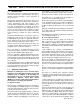
Welding Generator Load Bank Positive (+) Weld Output Terminal + − Negative (−) Weld Output Terminal − + Voltmeter And Ammeter Weld Cables S-0456 Diagram 8-1. Load Bank Connections 10. Stop engine, and disconnect load bank cables. 11. Allow exhaust system to cool. 12. Inspect inside of exhaust pipe. If pipe is dry, the run-in procedure is complete. If pipe is coated with a wet, black, tar-like substance, repeat runin procedure.
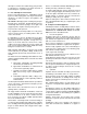
Welding Generator Voltmeter And Ammeter (If so equipped) Resistance Grid Input And Output Receptacles Weld Output Terminals (Polarity Not Important) Weld Cables ♦ Clamp-On DC Ammeter V ♦ Voltmeter A ♦ Required if welding generator is not equipped with meters. S-0457 Diagram 8-2. Resistance Grid Connections SECTION 9 − TROUBLESHOOTING 9-1.
6. Start engine following procedures outlined in Section 7 (Sequence of Operation) of this manual. If the unit does not start after cranking for twenty seconds, stop the jump starting procedure. More than twenty seconds seldom starts the engine unless some mechanical adjustment is made. If CB3 opens, 115 volts ac output to socket/terminal D of REMOTE 9 receptacle RC3 and terminal strip 3T stops, and the remote amperage/voltage control will not function. C.
9-5. The following tables are designed to diagnose and provide remedies for some of the troubles that may develop in this welding generator. TROUBLESHOOTING (Tables 9-1 Thru 9-4) WARNING: ELECTRIC SHOCK can kill. • Do not touch live electrical parts. • Use these tables in conjunction with the circuit diagram while performing troubleshooting procedure. If the trouble is not remedied after performing these procedures, contact the nearest Factory Authorized Service Station/Service Distributor.
Table 9-2. Auxiliary Power Troubleshooting AUXILIARY POWER TROUBLE PROBABLE CAUSE No 120 volt output at 3T termi- Circuit breaker CB1 open. nals L and M. Poor contact between slip rings and brushes. REMEDY Reset CB1 (see Section 9-3). Clean slip rings (see Section 8-9). Replace brushes according to Section 8-9. High auxiliary power output voltage. High engine speed. Check and adjust engine speed according to Section 8-8. (Maximum voltages should not exceed 132 volts for single-phase power.
NOTES OM-166 941 Page 35
SECTION 10 − ELECTRICAL DIAGRAMS Diagram 10-1.
SC-168 908-B OM-166 941 Page 37
OM-166 941 Page 38 Figure 11-1A.
Item No. Dia. Mkgs. Part No. Description Quantity Figure 11-1A. Main Assembly ... ... ... ... ... ... ... ... ... ... ... ... ... 1 2 3 4 5 6 7 8 9 10 11 12 13 . . . . . . . . . . . . . . . . . . . 134 834 . . . . . . . . . . . . . . . . . . . 131 123 . . . . . . . . . . . . . . . . . . . 146 240 . . . . . . . . . . . . 1063920009309 . . . . . . . . . . . . 0302390009309 . . . . . . . . . . . . 1261610009309 . . . . . . . . . . . . 1448660009309 . . . . . . . . . . . . 1448670009309 . . . . . . . . .
Item No. Dia. Mkgs. Part No. Description Quantity Figure 11-1A. Main Assembly (Continued) . . . 49 . . . . . . . . . . . . . . . . . . . 073 433 . . . 50 . . . . . . . . . . . . 0456660009309 . . . 51 . . . . . . . . . . . . 1187900009309 . . . 52 . . . . . . . . . . . . . . . . . . . 010 914 . . . 53 . . . . . . . . . . . . . . . . . . . 087 341 . . . 54 . . . . . . . . . . . . 1551660009309 . . . . . . . . . . . . . . . . . . . . . . . . . 121 699 . . . . . . . . . . . . . . . . . . . . . . . . .
Item No. Dia. Mkgs. Part No. Description Quantity Figure 11-1B. Main Assembly ... ... ... ... ... 1 2 3 4 5 . . . . . . . . . . . . 1448720009309 . . . . . . . . . . . . . . . . . . . . . 006 086 . . .............................. . . . . . . . . . . . . 1448200009309 . . . . . . . . . . . . . . . . . . . . . 138 098 . . . . . 6 . . . . . . . . . . . . . . . . . . . 192 197 . . . 7 . . . . . . . . . . . . 1187060009309 . . . 8 . . . . . . . . . . . . . . . . . . . 023 313 . . . 9 . . . . . . . . . .
Figure 11-1B.
Item No. Dia. Mkgs. Part No. Description Quantity Figure 11-1B. Main Assembly (Continued) ... ... ... ... ... ... ... ... ... ... ... ... ... ... ... ... ... ... ... ... 49 50 51 52 53 54 55 56 57 58 59 60 61 62 63 64 65 66 67 68 . . . . . . . . . . . . . . . . . . . 089 351 . . . . . . . . . . . . 1532480009309 . . . . . . . . . . . . 1528480009309 . . . . . . . . . . . . 1528520009309 . . . . . . . . . . . . . . . . . . . 071 890 . . . . . . . . . . . . 1529040009309 . . . . . . . . . . . .
1 2 3* 5 6 24 25 7 23 22 21 8 9 20 4 10 19 9 11 18 17 16 15 14 13 12 *Includes Item 4 Figure 11-2.
Item No. Dia. Mkgs. Part No. Description Quantity Figure 11-2. Panel, Front w/Components (Fig 11-1A Item 75) . . . 1 . . . . S9 . . . . 1346300009880 . . SWITCH, range . . . . . . . . . . . . . . . . . . . . . . . . . . . . . . . . . . . . . . . . . . . . . . 2 . . . . . . . . . . . . 1183400010202 . . PANEL, front upper . . . . . . . . . . . . . . . . . . . . . . . . . . . . . . . . . . . . . . . . . . . 3 . . . . R1 . . . . . . . . . . . 072 462 . . POTENTIOMETER, w/shaft lock (consisting of) . . . .
8 1 2 9 7 10 6 2 3 4 11 5 12 13 14 10 15 16 1 31 30 17 27 28 29 18 26 19 20 23 25 22 21 24 Figure 11-3.
Item No. Dia. Mkgs. Part No. Description Quantity Figure 11-3. Panel, Lower Front w/Components (Fig 11-1A Item 66) . . . 1 . . . . . . . . . . . . 0386120009309 . . . 2 . . . . . . . . . . . . . . . . . . . 601 840 . . . 3 . . . . . . . . . . . . . . . . . . . 601 839 . . . 4 . . . . . . . . . . . . . . . . . . . 038 847 . . . 5 . . Neg/Pos . . . . . . . . 038 613 . . . 6 . . . . . . . . . . . . . . . . . . . 038 900 . . . 7 . . . . . . . . . . . . . . . . . . . 602 247 . . . 8 . . . . . . . . . . . .
Item No. Dia. Mkgs. Part No. Description Quantity Figure 11-4. Control Box (Fig 11-1A Item 65) . . . 1 . . . . . . . . . . . . 1186380009309 . . . 2 . . . . T1 . . . . 0700700009309 . . . 3 . . . . RC6 . . . . . . . . . . 090 246 . . . . . . . . . . . . . . . . . . . . . . . . . 079 535 . . . 4 . . . . RC7 . . . . . . . . . . 047 637 . . . . . . . . . . . . . . . . . . . . . . . . . 079 534 . . . 5 . . . . D1 . . . . . . . . . . . 189 701 . . . 6 . . . . . . . . . . . . 1562370009309 . . . 7 . . . .
Item No. Part No. Description Quantity Figure 11-5. Generator (Fig 11-1B Item 72) ... ... ... ... ... ... ... ... ... ... ... ... ... ... ... ... ... 1 2 3 4 5 6 7 8 9 10 11 12 13 14 15 16 17 . . . . . . . . . . . . . . . 018 614 . . . . . . . . . . . . . . *151 299 . . . . . . . . . . . . . . . 600 270 . . . . . . . . . . . . . . . 152 044 . . . . . . . . . . . . . . . 049 650 . . . . . . . . . . . . . . . 013 367 . . . . . . . . . . . . . . +140 096 . . . . . . . . . . . . . . . 039 207 . . . . . .
Notes