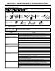
OM-1600 199 525 September 2000 Processes TIG (GTAW) Welding Description TIG Torch Diamondback Series GTAW Torches DB1712R, DB1725R, DB17V25R, DB17V12-2 And DB17V25-2 Visit our website at www.MillerWelds.
TABLE OF CONTENTS WARNING This product, when used for welding or cutting, produces fumes or gases which contain chemicals known to the State of California to cause birth defects and, in some cases, cancer. (California Health & Safety Code Section 25249.5 et seq.) SECTION 1 –SAFETY PRECAUTIONS FOR GTAW TORCHES – READ BEFORE USING . . . . . . . 1-1. Symbol Usage . . . . . . . . . . . . . . . . . . . . . . . . . . . . . . . . . . . . . . . . . . . . . . . . . . . . . . . . . . . . . . . . 1-2.
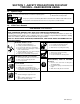
SECTION 1 –SAFETY PRECAUTIONS FOR GTAW TORCHES – READ BEFORE USING SR6_1/00 1-1. Symbol Usage Means Warning! Watch Out! There are possible hazards with this procedure! The possible hazards are shown in the adjoining symbols. Y Marks a special safety message. . Means NOTE; not safety related. This group of symbols means Warning! Watch Out! Possible ELECTRIC SHOCK and HOT PARTS hazards. Consult symbols and related instructions below for necessary actions to avoid the hazards. 1-2.
EMF INFORMATION Considerations About Welding And The Effects Of Low Frequency Electric And Magnetic Fields Welding current, as it flows through welding cables, will cause electromagnetic fields. There has been and still is some concern about such fields.
SECTION 2 – SPECIFICATIONS 2-1. Specifications Specification Model Description Description Diamondback Series TIG Torch – Model DB17: 150 Ampere Rating; Available With 12-1/2 ft (3.8 m) or 25 ft (7.6 m) One-Piece, High-Flex Cable Diamondback Series TIG Torch – Model DB17V: TIG Torch With Gas Valve; 150 Ampere Rating; Available With 25 ft (7.6 m) One-Piece, High-Flex Cable; Or 12-1/2 ft (3.8 m) or 25 ft (7.6 m) Two-Piece, High-Flex Cable.
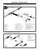
SECTION 3 – INSTALLATION 3-1. Required Torch Parts And Torch Assembly 7 Assembling Torch Parts 6 5 4 3 2 1 13 9 15 10 14 8 Or 12 Ref. ST-802 566-B 11 1 2 3 4 5 6 7 8 9 Cup Collet Body Heat Shield Backcap Insulator Collet O-Ring Backcap Torch Body Handle 10 One-Piece Power Cable 11 Power Cable Adapter 12 International Style Flow-Through Adapter Note: Adapter needed only if torch is equipped with one-piece cable.
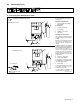
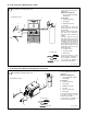
3-3. Connecting Torch A. Connecting Torch With One-Piece Cable Turn Off welding power source, and disconnect input power before installing torch. Obtain the following hose: If applicable, install high-frequency unit. 2 4 Torch Without Gas Valve 1 3 Gas Hose With 5/8-18 RightHand Fittings Connections: 5 2 Regulator/Flowmeter 3 Gas Cylinder 4 Welding Power Source 5 Gas Valve Operating Torch Gas Valve: Valve controls gas preflow and postflow. Open valve on torch just before welding.
B. Connecting Torch With Two-Piece Cable Turn Off welding power source, and disconnect input power before installing torch. Obtain the following hose: If applicable, install high-frequency unit. 1 Torch With Gas Valve Connections: 4 2 5 Gas Hose With 5/8-18 RightHand Fittings 3 6 1 2 Regulator/Flowmeter 3 Gas Cylinder 4 Welding Power Source 5 Gas Valve Valve controls gas preflow and postflow. Open valve on torch just before welding.
SECTION 4 – MAINTENANCE & TROUBLESHOOTING 4-1. Routine Maintenance Y Disconnect torch before maintaining. 40 Hours Clean and tighten weld terminals. Repair or replace cracked weld cable. Replace unreadable labels. Replace cracked parts Torch Body Torch Cable 4-2. Troubleshooting NOTE Before using troubleshooting table, check selection and preparation of tungsten electrode according to Section 5. Trouble Remedy Arc will not start. High frequency present Check cable and work connections.
Trouble Wandering arc Remedy Shield weld zone from drafts. Reduce gas flow rate. Select proper size and type of tungsten. Properly prepare tungsten according to Section 5. When using AC, check welding power source High Frequency control setting, and increase setting if necessary. Yellow powder or smoke on cup. Use proper type shielding gas. Check for proper gas flow rate. Check manufacture’s recommendations. Increase postflow time. Check torch cup size. Match cup size to joint being welded.
SECTION 5 – SELECTING AND PREPARING TUNGSTEN ELECTRODE FOR DC OR AC WELDING ac/dc_gtaw 2/2000 Y Whenever possible and practical, use DC weld output instead of AC weld output. 5-1. Selecting Tungsten Electrode (Wear Clean gloves To Prevent Contamination Of Tungsten ) Amperage Range - Gas Type♦ - Polarity Electrode Diameter DC – Argon – Electrode Negative/Straight Polarity DC – Argon – Electrode Positive/Reverse Polarity AC – Argon AC – Argon – .010” Up to 25 * Up to 20 Up to 15 .
5-2. Preparing Tungsten Electrode For Welding Y Grinding the tungsten electrode produces dust and flying sparks which can cause injury and start fires. Use local exhaust (forced ventilation) at the grinder or wear an approved respirator. Read MSDS for safety information. Consider using tungsten containing ceria, lanthana, or yttria instead of thoria. Grinding dust from thoriated electrodes contains low-level radioactive material. Properly dispose of grinder dust in an environmentally safe way.
SECTION 6 – GUIDELINES FOR TIG WELDING (GTAW) 6-1. Positioning The Torch Y Weld current can damage electronic parts in vehicles. Disconnect both battery cables before welding on a vehicle. Place work clamp as close to the weld as possible. . For additional information, see 3 your distributor for a handbook on the Gas Tungsten Arc Welding (GTAW) process. 2 1 Workpiece Make sure workpiece is clean before welding. 4 2 Work Clamp Place as close to the weld as possible.
6-2. Torch Movement During Welding Tungsten Without Filler Rod 75° Welding direction Form pool Tilt torch Move torch to front of pool. Repeat process. Tungsten With Filler Rod 75° Welding direction Form pool Tilt torch Remove rod 15° Add filler metal Move torch to front of pool. Repeat process.
6-3.
SECTION 7 – PARTS LIST 1 7 3 4 8 6 2 9 5 10 14 15 12 11 11 13 11 16 or 17 802 567-A Figure 7-1. Complete Torch Assembly Table 7-1. Tungsten Electrodes Tungsten Electrodes – 7 Inches Long Diameter Pure (Green) 2% Thor. (Red) .
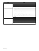
Quantity Model Item No. Stock No. Description DB DB 1725R 1712R DB 17V25R DB DB 17V25-2 17V12-2 Figure 7-1. Complete Torch Assembly . . 1 . . . . . . 57Y02 . . . . . . . BACK CAP, long (consisting of) . . . . . . . . . . . . . . 1 . . . . 1 . . . . . 1 . . . . . 1 . . . . . . . 2 . . . . . ♦57Y04 . . . . . . . BACK CAP, button (consisting of) . . . . . . . . . . . . 1 . . . . 1 . . . . . 1 . . . . . 1 . . . . . . . . . . . . . . 199 591 . . . . . . . . . O-RING . . . . . . . . . . . . . . . . . . . .
Effective January 1, 2000 (Equipment with a serial number preface of “LA” or newer) This limited warranty supersedes all previous Miller warranties and is exclusive with no other guarantees or warranties expressed or implied. Warranty Questions? Call 1-800-4-A-MILLER for your local Miller distributor. Your distributor also gives you ... Service You always get the fast, reliable response you need. Most replacement parts can be in your hands in 24 hours.
Owner’s Record Please complete and retain with your personal records. Model Name Serial/Style Number Purchase Date (Date which equipment was delivered to original customer.) Distributor Address City State Zip For Service Call 1-800-4-A-Miller or see our website at www.MillerWelds.com to locate a DISTRIBUTOR or SERVICE AGENCY near you. Always provide Model Name and Serial/Style Number.