OM-234 388B 2007−08 ® Auto-Darkening Helmets Model: Digital Elitet To help us serve you better, go to www.MillerWelds.
TABLE OF CONTENTS SECTION 1 − SAFETY PRECAUTIONS − READ BEFORE USING . . . . . . . . . . . . . . . . . . . . . . 1 1-1. Symbol Usage . . . . . . . . . . . . . . . . . . . . . . . . . . . . . . . . . . . . . . . . . . . . . . . . . . . . . . . . . . . . 1 1-2. Hazards . . . . . . . . . . . . . . . . . . . . . . . . . . . . . . . . . . . . . . . . . . . . . . . . . . . . . . . . . . . . . . . . . 1 SECTION 2 − SPECIFICATIONS . . . . . . . . . . . . . . . . . . . . . . . . . . . . . . . . . . . . . . . . . . .
SECTION 1 − SAFETY PRECAUTIONS − READ BEFORE USING Protect yourself and others from injury — read and follow these precautions. 1-1. Symbol Usage DANGER! − Indicates a hazardous situation which, if not avoided, will result in death or serious injury. The possible hazards are shown in the adjoining symbols or explained in the text. . Indicates special instructions. Indicates a hazardous situation which, if not avoided, could result in death or serious injury.
SECTION 2 − SPECIFICATIONS Viewing Field 97 x 60mm/3.81 x 2.62 in Reaction Time 0.0000500sec (1/20,000) Operating Modes 4 Modes: Weld, Cutting, Grind, X Mode Available Shades Weld Mode: All shades provide continuous UV and IR protection. Darkened State: No. 8 − No. 13 Light State: No. 3 Cutting Mode: Darkened State: No. 5 − No. 8 Light State: No. 3 Grind Mode: Light State: No. 3 X Mode: Darkened State: No. 8 − No. 13 Light State: No.
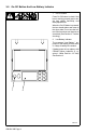
SECTION 3 − OPERATING INSTRUCTIONS 3-1. Helmet Controls 1 On-Off Button (See Section 3-2) Mode Control Button (See Section 3-3) Display Screen Variable Shade Control Buttons (See Section 3-4) Sensitivity Control Buttons (See Section 3-5) Lens Delay Control Buttons (See Section 3-6) 2 3 4 5 6 . The lens assembly saves the shade, sensitivity, and delay settings when the lens turns off.
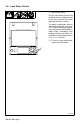
3-2. On-Off Button And Low Battery Indicator 1 On-Off Button Press On-Off button to check if the lens is working properly and to begin lens shade, sensitivity, and delay adjustments. When the On-Off button is pressed, the lens should darken and return to the clear state. Do not use the helmet if the lens does not function as described. (See Section 9, Troubleshooting.) 2 Low Battery Indicator The message “Low Battery” appears on the display screen when 2−3 days of battery life remains.
3-3. Mode Control 1 Mode Control Button Press button to select the mode appropriate for the work activity: Weld Mode − used for most welding applications. In this mode the lens turns on when it optically senses a welding arc. Adjust shade, sensitivity, and delay settings as needed. Cutting Mode − used for cutting applications. In this mode the lens turns on when it optically senses a cutting arc. Adjust shade, sensitivity, and delay settings as needed. Grind Mode − used for metal grinding applications.
3-4. Variable Shade Control 1 Shade Control Buttons Use the shade control Down and Up buttons to select the lens shade in the darkened state. The shade ranges for each mode are as follows: Weld − No. 8 − No. 13 Cutting − No. 5 − No. 8 Grind − No. 3 only X Mode − No. 8 − No. 13 1 Start at the highest setting and adjust lighter to suit the application and your personal preference. Use the table below to select proper shade control setting based on your welding process.
3-5. Sensitivity Control 1 Sensitivity Control Buttons Use Sensitivity Control Low and Hi buttons to make the lens more responsive to different light levels in various welding processes. Use a sensitivity setting of 5 for most applications. The sensitivity ranges for each mode are as follows: Weld, Cutting, X Modes − 0 − 10 Grind Mode − No sensitivity adjustment It may be necessary to adjust helmet sensitivity to accommodate different lighting conditions or if lens is flashing On and Off.
3-6. Lens Delay Control 1 Lens Delay Control Use the Lens Delay Control Fast and Slow buttons to adjust the time for the lens to switch to the clear state after welding or cutting. The delay is particularly useful in eliminating bright after-rays present in higher amperage applications where the molten puddle remains bright momentarily after welding. Use the Lens Delay Control buttons to adjust delay from 0 to 10 (0.1 to 1.0 second). . There is no lens delay adjustment in the Grind mode.
3-7. Lens Adjustment Procedure . Lens assembly displays prior settings when turned On. Retained settings are not shown in example. MODE . In the Grind mode the lens is a SHADE fixed shade No. 3. No lens adjustments are possible. SENSITIVITY Adjusting Lens Assembly: DELAY MODE WELD SHADE SENSITIVITY S Turn lens On. Display screen appears. S Select mode (Weld, Cutting, Grind, X-Mode) S Select Shade By Pressing Down/Up Buttons. S Select Sensitivity By Pressing Low/Hi Buttons.
SECTION 4 − ADJUSTING HEADGEAR . There are four headgear adjust- ments: headgear top, tightness, angle adjustment, and distance adjustment. 1 Headgear Top Adjusts headgear for proper depth on the head to ensure correct balance and stability. 1 3 2 Headgear Tightness To adjust, push in the adjusting knob located on the back of the headgear and turn left or right to desired tightness. . If adjustment is limited, it may be necessary to remove the comfort cushion.
SECTION 5 − REPLACING THE LENS COVERS Be sure wide edge of gasket faces helmet shell. Be sure flat side of gasket faces helmet shell. 6 5 4 3 2 1 Ref. 805 012 ! Never use the autodarkening lens without the inside and outside lens covers properly installed. Welding spatter will damage the auto-darkening lens and void the warranty.
SECTION 6 − REPLACING THE BATTERY To replace the batteries, remove the auto-darkening lens assembly (see Section 5). 1 After removing the lens assembly, slide the battery holding trays out and remove the old batteries. 1 + + Be sure Positive (+) side of battery faces up. Battery Tray Replace with CR2450 lithium type batteries (2 required) or equivalent (Miller Part No. 217043). . Be sure Positive (+) side of the battery faces up (toward inside of helmet). Reinstall the battery trays.
SECTION 7 − INSTALLING OPTIONAL MAGNIFYING LENS 1 Optional Magnifying Lens Starting at the top, slide magnifying lens into the helmet retaining brackets. Align the magnifying lens with the auto-darkening lens assembly. 1 Reverse procedure to remove magnifying lens. . To prevent lens fogging, install flat side of magnifying lens toward auto-darkening lens. 805 011 SECTION 8 − MAINTENANCE NOTICE − Never use solvents or abrasive cleaning detergents. NOTICE − Do not immerse the lens assembly in water.
SECTION 9 − TROUBLESHOOTING Trouble Remedy Auto lens not ON – autolens does not darken momentarily when the On button is pressed. Check batteries and verify they are in good condition and installed properly. Not switching – auto-lens stays light and does not darken when welding or cutting. Stop welding or cutting immediately: Make sure the lens is turned On. Check battery surfaces and contacts, and clean if necessary. Check battery for proper contact and gently adjust contact points if necessary.
SECTION 10 − PARTS LIST 11 8 10 12 9 Miller 7 2 3 5 13 6 4 1 804 111 Figure 10-1.
Item No. Part No. Description Quantity Figure 10-1. Digital Elite Auto-Darkening Welding Helmet 1 . . . . . . . . . . . . 216 331 . . . . . . . . Helmet Shell, Black . . . . . . . . . . . . . . . . . . . . . . . . . . . . . . 1 . . . . . . . . . . . . 227 189 . . . . . . . . Helmet Shell, The Joker . . . . . . . . . . . . . . . . . . . . . . . . . . . 1 . . . . . . . . . . . . 234 066 . . . . . . . . Helmet Shell, Stars And Stripes II . . . . . . . . . . . . . . . . . . . 1 . . . . . . . . . . . .
SECTION 11 − LIMITED WARRANTY Effective January 1, 2007 LIMITED WARRANTY – Subject to the terms and conditions below. Miller Electric Mfg. Co., Appleton, Wisconsin, warrants to its original retail purchaser that the new Miller equipment sold after the effective date of this limited warranty is free of defects in material and workmanship at the time it is shipped by Miller.
Visit our website at www.MillerWelds.com ® Miller Electric Mfg. Co. An Illinois Tool Works Company 1635 West Spencer Street Appleton, WI 54914 USA PRINTED IN USA © 2007 Miller Electric Mfg. Co.