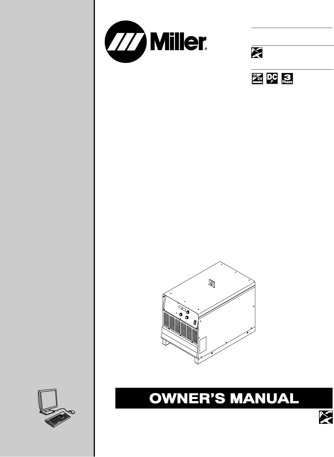
OM-240 044D 2013−04 Processes Multiprocess Welding Description Arc Welding Power Source Dimension NTt450 WCC File: Multiprocess Welding Visit our website at www.MillerWelds.
From Miller to You Thank you and congratulations on choosing Miller. Now you can get the job done and get it done right. We know you don’t have time to do it any other way. That’s why when Niels Miller first started building arc welders in 1929, he made sure his products offered long-lasting value and superior quality. Like you, his customers couldn’t afford anything less. Miller products had to be more than the best they could be. They had to be the best you could buy.
TABLE OF CONTENTS SECTION 1 − SAFETY PRECAUTIONS - READ BEFORE USING . . . . . . . . . . . . . . . . . . . . . . . . . . . . . . . . . . . 1-1. Symbol Usage . . . . . . . . . . . . . . . . . . . . . . . . . . . . . . . . . . . . . . . . . . . . . . . . . . . . . . . . . . . . . . . . . . . . . . . . 1-2. Arc Welding Hazards . . . . . . . . . . . . . . . . . . . . . . . . . . . . . . . . . . . . . . . . . . . . . . . . . . . . . . . . . . . . . . . . . . 1-3.
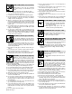
SECTION 1 − SAFETY PRECAUTIONS - READ BEFORE USING som 2011−10 7 Protect yourself and others from injury — read, follow, and save these important safety precautions and operating instructions. 1-1. Symbol Usage DANGER! − Indicates a hazardous situation which, if not avoided, will result in death or serious injury. The possible hazards are shown in the adjoining symbols or explained in the text. Indicates a hazardous situation which, if not avoided, could result in death or serious injury.
FUMES AND GASES can be hazardous. Welding produces fumes and gases. Breathing these fumes and gases can be hazardous to your health. Keep your head out of the fumes. Do not breathe the fumes. If inside, ventilate the area and/or use local forced ventilation at the arc to remove welding fumes and gases. If ventilation is poor, wear an approved air-supplied respirator.
1-3. Additional Symbols For Installation, Operation, And Maintenance FIRE OR EXPLOSION hazard. BATTERY EXPLOSION can injure. Do not install or place unit on, over, or near combustible surfaces. Do not install unit near flammables. Do not overload building wiring − be sure power supply system is properly sized, rated, and protected to handle this unit. Do not use welder to charge batteries or jump start vehicles unless it has a battery charging feature designed for this purpose.
1-4. California Proposition 65 Warnings Welding or cutting equipment produces fumes or gases which contain chemicals known to the State of California to cause birth defects and, in some cases, cancer. (California Health & Safety Code Section 25249.5 et seq.) This product contains chemicals, including lead, known to the state of California to cause cancer, birth defects, or other reproductive harm. Wash hands after use. 1-5.
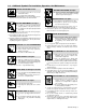
SECTION 2 − CONSIGNES DE SÉCURITÉ − LIRE AVANT UTILISATION fre_som_2011−10 7 Pour écarter les risques de blessure pour vous−même et pour autrui — lire, appliquer et ranger en lieu sûr ces consignes relatives aux précautions de sécurité et au mode opératoire. 2-1. Symboles utilisés DANGER! − Indique une situation dangereuse qui si on l’évite pas peut donner la mort ou des blessures graves. Les dangers possibles sont montrés par les symboles joints ou sont expliqués dans le texte.
Il reste une TENSION DC NON NÉGLIGEABLE dans les sources de soudage onduleur UNE FOIS l’alimentation coupée. Arrêter les convertisseurs, débrancher le courant électrique et décharger les condensateurs d’alimentation selon les instructions indiquées dans la partie Entretien avant de toucher les pièces. LES PIÈCES CHAUDES peuvent provoquer des brûlures. Ne pas toucher à mains nues les parties chaudes. Prévoir une période de refroidissement avant de travailler à l’équipement.
LES ACCUMULATIONS DE GAZ risquent de provoquer des blessures ou même la mort. Fermer l’alimentation du gaz comprimé en cas de non utilisation. Veiller toujours à bien aérer les espaces confinés ou se servir d’un respirateur d’adduction d’air homologué. Les CHAMPS ÉLECTROMAGNÉTIQUES (CEM) peuvent affecter les implants médicaux. Les porteurs de stimulateurs cardiaques et autres implants médicaux doivent rester à distance.
Les PIÈCES MOBILES peuvent causer des blessures. LE RAYONNEMENT HAUTE FRÉQUENCE (H.F.) risque de provoquer des interférences. Ne pas s’approcher des organes mobiles. Ne pas s’approcher des points de coincement tels que des rouleaux de commande. Le rayonnement haute fréquence (H.F.) peut provoquer des interférences avec les équipements de radio−navigation et de communication, les services de sécurité et les ordinateurs. LES FILS DE SOUDAGE peuvent provoquer des blessures.
2-5. Principales normes de sécurité Safety in Welding, Cutting, and Allied Processes, ANSI Standard Z49.1, is available as a free download from the American Welding Society at http://www.aws.org or purchased from Global Engineering Documents (phone: 1-877-413-5184, website: www.global.ihs.com). Safe Practices for the Preparation of Containers and Piping for Welding and Cutting, American Welding Society Standard AWS F4.1, from Global Engineering Documents (phone: 1-877-413-5184, website: www.global.ihs.com).
OM-240 044 Page 10
A complete Parts List is available at www.MillerWelds.com SECTION 3 − DEFINITIONS 3-1. Additional Safety Symbols And Definitions Some symbols are found only on CE products. Warning! Watch Out! There are possible hazards as shown by the symbols. Safe1 2012−05 Disconnect input plug or power before working on machine. Safe5 2012−05 GND/PE, Ground/Protective Earth Safe 114 2013−04 3-2.
A complete Parts List is available at www.MillerWelds.com SECTION 4 − SPECIFICATIONS 4-1. Serial Number And Rating Label Location The serial number and rating information for the power source is located on the front or the rear of the machine. Use the rating labels to determine input power requirements and/or rated output. For future reference, write serial number in space provided on back cover of this manual. 4-2.
A complete Parts List is available at www.MillerWelds.com 4-4. Duty Cycle And Overheating Duty Cycle is percentage of 10 minutes that unit can weld at rated load without overheating. If unit overheats, thermostat(s) opens, output stops, and cooling fan runs. Wait fifteen minutes for unit to cool. Reduce amperage or duty cycle before welding. NOTICE − Exceeding duty cycle can damage unit and void warranty.
A complete Parts List is available at www.MillerWelds.com 4-5. Volt-Ampere Curves Volt-ampere curves show minimum and maximum voltage and amperage output capabilities of unit. Curves of other settings fall between curves shown. A. CC Mode 90 80 70 DC Voltage 60 50 40 30 20 10 0 0 100 200 300 400 500 600 DC Current B.
A complete Parts List is available at www.MillerWelds.com SECTION 5 − INSTALLATION 5-1. Selecting A Location ! Special installation may be required where gasoline or volatile liquids are present − see NEC Article 511 or CEC Section 20. 1 2 Lifting Eye Lifting Forks Use lifting eye or lifting forks to move unit. Movement If using lifting forks, extend forks beyond opposite side of unit. 1 3 Line Disconnect Device Locate unit near correct input power supply. OR 2 Location 3 18 in.
A complete Parts List is available at www.MillerWelds.com 5-2. Tipping ! Do not move or operate unit where it could tip. ! Turn Off power before connecting to receptacle. 1 115 V 15 A AC Receptacle RC15 5-3. 115 VAC Receptacle And Supplementary Protectors Power is shared between RC15 and Remote 14 receptacle RC14 (see Section 5-7). 2 3 3 Supplementary Protector CB1 Supplementary Protector CB2 CB1 protects the 115 volts AC at RC15 from overload.
A complete Parts List is available at www.MillerWelds.com 5-4. Weld Output Terminals And Selecting Cable Sizes* NOTICE − The Total Cable Length in Weld Circuit (see table below) is the combined length of both weld cables. For example, if the power source is 100 ft (30 m) from the workpiece, the total cable length in the weld circuit is 200 ft (2 cables x 100 ft). Use the 200 ft (60 m) column to determine cable size.
A complete Parts List is available at www.MillerWelds.com 5-5. Connecting Weld Output Cables 2 6 1 3 4 Tools Needed: 5 3/4 in. (19 mm) 803 778-B ! Turn off power before connecting to weld output terminals. ! Failure to properly connect weld cables may cause excessive heat and start a fire, or damage your machine. 1 2 3 4 Do not place anything between weld cable terminal and copper bar. Make sure that the surfaces of the weld cable terminal and copper bar are clean.
A complete Parts List is available at www.MillerWelds.com 5-7. Connecting Remote Control ! Turn off power before connecting to Remote 14 receptacle. 1 Remote 14 Receptacle RC14 Connect remote control to RC14. 1 A B K J I H C L N D M G E F OR OR Ref. 800 166-D / Ref. S-0004-A / S-0750 Notes Work like a Pro! Pros weld and cut safely. Read the safety rules at the beginning of this manual.
A complete Parts List is available at www.MillerWelds.com 5-8. Electrical Service Guide Failure to follow these electrical service guide recommendations could create an electric shock or fire hazard. These recommendations are for a dedicated branch circuit sized for the rated output and duty cycle of the welding power source.
A complete Parts List is available at www.MillerWelds.
A complete Parts List is available at www.MillerWelds.com 5-10. Connecting 3-Phase Input Power 3 = GND/PE Earth Ground 9 8 11 10 2 4 7 1 IMPORTANT 3 Input Contactor 6 L1 L2 7 L3 4 5 4 3 = GND/ PE Earth Ground Tools Needed: 3/8 in. 3/8 in. input3 2013−04 − Ref. 803 766-C / 800 103-C / Ref.
A complete Parts List is available at www.MillerWelds.com 5-10. Connecting 3-Phase Input Power (Continued) ! ! Installation must meet all National and Local Codes − have only qualified persons make this installation. Disconnect and lockout/tagout input power before connecting input conductors from unit. Follow established procedures regarding the installation and removal of lockout/tagout devices. ! Make input power connections to the welding power source first.
A complete Parts List is available at www.MillerWelds.com SECTION 6 − OPERATION 6-1. Controls 2 4 7 3 5 6 1 239 918-D 1 Power Switch This unit is equipped with a fan motor that is thermostatically controlled and only runs when cooling is needed. 2 Voltmeter (see Section 6-2) 3 Ammeter (see Section 6-2) 4 Mode Switch Use Mode switch to determine both process and output On/Off control. Orange areas highlight “contactor on” positions.
A complete Parts List is available at www.MillerWelds.com 6-2. Meter Functions For CC/CV Models The meters display the actual weld output values for approximately three seconds after the arc is broken. Mode Meter Reading At Idle V A 78.0 Scratch Start TIG 85 Actual Volts (OCV) Preset Amps V A Lift-Arc TIG (GTAW) 8.0 85 Actual Volts Preset Amps V A 78.0 Air Carbon Arc 85 Actual Volts (OCV) Preset Amps V A 85 TIG (GTAW) Blank Preset Amps V A 24.
A complete Parts List is available at www.MillerWelds.com SECTION 7 − MAINTENANCE & TROUBLESHOOTING 7-1. Routine Maintenance ! Disconnect power before maintaining. Maintain more often during severe conditions. = Check = Change = Clean * To be done by Factory Authorized Service Agent Δ = Repair = Replace Every 3 Months Labels Weld Terminals Every 3 Months Δ Cables And Cords Every 6 Months :Durning heavy service, clean monthly. 7-2.
A complete Parts List is available at www.MillerWelds.com 7-3. Voltmeter/Ammeter Help Displays All directions are in reference to the front of the unit. All circuitry referred to is located inside the unit. 1 V 1 A HE.L P−0 V A HE.L P−2 V A 2 3 HE.L P−3 V A HE.L P−4 V A HE.L P−5 V A HE.L P−6 V A HE.L P−7 V A HE.L P−9 5 4 8 Help 4 Display Indicates a malfunction in the thermal protection circuitry located on the secondary heat sink of the unit.
A complete Parts List is available at www.MillerWelds.com 7-4. Troubleshooting Trouble No weld output; unit completely inoperative; pilot light PL1 off. Remedy Place line disconnect device in On position (see Section 5-10). Check for open line fuse(s), and replace if open (see Section 5-10). Check for proper input power connections (see Section 5-10). Check for proper jumper link position (see Section 5-9). Check fuse F1, and replace if necessary (see Section 7-2). Meter displays a HELP message.
A complete Parts List is available at www.MillerWelds.com SECTION 8 − PARTS LIST 8-1. Recommended Spare Parts Dia. Mkgs. Part No. Description Quantity Recommended Spare Parts . . . . . . . . . . F1 . . 156065 . . . . Fuse Crtg, .5 amp 600 V time delay . . . . . . . . . . . . . . . . . . . . . . . . . . . . . .
A complete Parts List is available at www.MillerWelds.com SECTION 9 − ELECTRICAL DIAGRAM Figure 9-1.
A complete Parts List is available at www.MillerWelds.
Notes
Notes
Notes
Effective January 1, 2013 (Equipment with a serial number preface of MD or newer) Warranty Questions? Call 1-800-4-A-MILLER for your local Miller distributor. Your distributor also gives you ... Service You always get the fast, reliable response you need. Most replacement parts can be in your hands in 24 hours. Support Need fast answers to the tough welding questions? Contact your distributor. The expertise of the distributor and Miller is there to help you, every step of the way.
Owner’s Record Please complete and retain with your personal records. Model Name Serial/Style Number Purchase Date (Date which equipment was delivered to original customer.) Distributor Address City State Zip For Service Contact a DISTRIBUTOR or SERVICE AGENCY near you. Always provide Model Name and Serial/Style Number. Contact your Distributor for: Welding Supplies and Consumables Options and Accessories Personal Safety Equipment Service and Repair Miller Electric Mfg. Co.