OM-2252 218 084R 2008−01 Processes Multiprocess Welding Description Arc Welding Power Source Dimension NT 450 And t Dimension NT 500 t File: Multiprocess Welding Visit our website at www.MillerWelds.
From Miller to You Thank you and congratulations on choosing Miller. Now you can get the job done and get it done right. We know you don’t have time to do it any other way. That’s why when Niels Miller first started building arc welders in 1929, he made sure his products offered long-lasting value and superior quality. Like you, his customers couldn’t afford anything less. Miller products had to be more than the best they could be. They had to be the best you could buy.
TABLE OF CONTENTS SECTION 1 − SAFETY PRECAUTIONS - READ BEFORE USING . . . . . . . . . . . . . . . . . . . . . . . . . . . . . . . . . . . 1-1. Symbol Usage . . . . . . . . . . . . . . . . . . . . . . . . . . . . . . . . . . . . . . . . . . . . . . . . . . . . . . . . . . . . . . . . . . . . . . . . 1-2. Arc Welding Hazards . . . . . . . . . . . . . . . . . . . . . . . . . . . . . . . . . . . . . . . . . . . . . . . . . . . . . . . . . . . . . . . . . . 1-3.
Notes
SECTION 1 − SAFETY PRECAUTIONS - READ BEFORE USING som _2007−04 7 Protect yourself and others from injury — read and follow these precautions. 1-1. Symbol Usage DANGER! − Indicates a hazardous situation which, if not avoided, will result in death or serious injury. The possible hazards are shown in the adjoining symbols or explained in the text. Indicates a hazardous situation which, if not avoided, could result in death or serious injury.
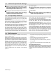
FUMES AND GASES can be hazardous. Welding produces fumes and gases. Breathing these fumes and gases can be hazardous to your health. Keep your head out of the fumes. Do not breathe the fumes. If inside, ventilate the area and/or use local forced ventilation at the arc to remove welding fumes and gases. If ventilation is poor, wear an approved air-supplied respirator.
1-3. Additional Symbols For Installation, Operation, And Maintenance FIRE OR EXPLOSION hazard. Do not install or place unit on, over, or near combustible surfaces. Do not install unit near flammables. Do not overload building wiring − be sure power supply system is properly sized, rated, and protected to handle this unit. FALLING UNIT can cause injury. MOVING PARTS can cause injury. Keep away from moving parts such as fans. Keep all doors, panels, covers, and guards closed and securely in place.
1-4. California Proposition 65 Warnings Welding or cutting equipment produces fumes or gases which contain chemicals known to the State of California to cause birth defects and, in some cases, cancer. (California Health & Safety Code Section 25249.5 et seq.) Battery posts, terminals and related accessories contain lead and lead compounds, chemicals known to the State of California to cause cancer and birth defects or other reproductive harm. Wash hands after handling.
SECTION 2 − CONSIGNES DE SÉCURITÉ − LIRE AVANT UTILISATION fre_som_2007−04 7 Se protéger et protéger les autres contre le risque de blessure — lire et respecter ces consignes. 2-1. Symboles utilisés DANGER! − Indique une situation dangereuse qui si on l’évite pas peut donner la mort ou des blessures graves. Les dangers possibles sont montrés par les symboles joints ou sont expliqués dans le texte. Indique une situation dangereuse qui si on l’évite pas peut donner la mort ou des blessures graves.
Il reste une TENSION DC NON NÉGLIGEABLE dans les sources de soudage onduleur quand on a coupé l’alimentation. Arrêter les convertisseurs, débrancher le courant électrique et décharger les condensateurs d’alimentation selon les instructions indiquées dans la partie Entretien avant de toucher les pièces. DES PIÈCES CHAUDES peuvent provoquer des brûlures graves. Ne pas toucher à mains nues les parties chaudes. Prévoir une période de refroidissement avant de travailler à l’équipement.
LES ACCUMULATIONS DE GAZ risquent de provoquer des blessures ou même la mort. Protéger les bouteilles de gaz comprimé d’une chaleur excessive, des chocs mécaniques, des dommages physiques, du laitier, des flammes ouvertes, des étincelles et des arcs. Fermer l’alimentation du gaz protecteur en cas de non-utilisation. Veiller toujours à bien aérer les espaces confinés ou se servir d’un respirateur d’adduction d’air homologué.
LES FILS DE SOUDAGE peuvent provoquer des blessures. LE RAYONNEMENT HAUTE FRÉQUENCE (H.F.) risque de provoquer des interférences. Ne pas appuyer sur la gâchette avant d’en avoir reçu l’instruction. Ne pas diriger le pistolet vers soi, d’autres personnes ou toute pièce mécanique en engageant le fil de soudage. DES ORGANES MOBILES peuvent provoquer des blessures. S’abstenir de toucher des organes mobiles tels que des ventilateurs.
2-5. Principales normes de sécurité Safety in Welding, Cutting, and Allied Processes, ANSI Standard Z49.1, de Global Engineering Documents (téléphone : 1-877-413-5184, site Internet : www.global.ihs.com). Recommended Safe Practices for the Preparation for Welding and Cutting of Containers and Piping, American Welding Society Standard AWS F4.1 de Global Engineering Documents (téléphone : 1-877-413-5184, site Internet : www.global.ihs.com).
OM-2252 Page 10
SECTION 3 − DEFINITIONS 3-1. General Precautionary Label Warning! Watch Out! There are possible hazards as shown by the symbols. 1 1.1 1.2 1.3 2 2.1 2.2 2.3 3 3.1 3.2 3.3 4 4.1 5 6 Electric shock from welding electrode or wiring can kill. Wear dry insulating gloves. Do not touch electrode with bare hand. Do not wear wet or damaged gloves. Protect yourself from electric shock by insulating yourself from work and ground. Disconnect input plug or power before working on machine.
3-2. Input Connection Label 1/96 1 2 3 4 1 Warning! Watch Out! There are possible hazards as shown by the symbols. Electric shock from wiring can kill. Disconnect input plug or power before working on machine. Read the Owner’s Manual before working on this machine. Consult rating label for input power requirements, and check power available at the job site − they must match. Read Owner’s Manual and inside labels for connection points and procedures.
SECTION 4 − INSTALLATION 4-1. Specifications Rated Welding Output Model Amperage/ Voltage Range 5 − 500A In CC Mode 450 Amp 450 A @ 38 Volts DC DC, 100% Duty Cycle 10 − 38V In CV Mode Amperes Input at Rated Load Output 50/60 Hz, Three-Phase Max OCV−DC 230 V 380 V 400 V 440 V 460 V 575 V KVA KW 78 VDC In CC Mode For 60 Hz 80 VDC In CC Mode For 50 Hz 78 VDC In CV Mode For 60 Hz 57 34 33 30 29 23 22.6 21.0 *2.18 *1.11 *1.05 *.950 *1.04 *0.84 *0.87 *0.
4-3. Volt-Ampere Curves Volt-ampere curves show minimum and maximum voltage and amperage output capabilities of unit. Curves of other settings fall between curves shown. A. CC Mode 90 80 70 DC Voltage 60 50 40 30 20 10 0 0 100 200 300 400 500 600 DC Current B.
4-4. Selecting A Location 1 2 Lifting Eye Lifting Forks Use lifting eye or lifting forks to move unit. Movement If using lifting forks, extend forks beyond opposite side of unit. 1 3 4 OR Plate Label Rating Label CE Models − Typical Use rating label to determine input power needs. 2 5 Line Disconnect Device Locate unit near correct input power supply.
4-5.
4-6. Tipping ! Do not move or operate unit where it could tip. ! Turn Off power before connecting to receptacle. 1 115 V 15 A AC Receptacle RC15 4-7. 115 VAC Receptacle And Circuit Breakers Power is shared between RC15 and Remote 14 receptacle RC14 (see Section 4-11). 3 2 2 3 Circuit Breaker CB1 Circuit Breaker CB2 CB1 protects the 115 volts ac portion of RC14 and RC15 from overload. CB2 protects the 24 volts ac portion of RC14 from overload. Press button to reset breaker. 1 Ref.
4-8. Weld Output Terminals And Selecting Cable Sizes ! Total Cable (Copper) Length In Weld Circuit Not Exceeding Turn Off power before connecting to weld output terminals.
4-10. Remote 14 Receptacle Information Socket* 24 VOLTS AC 115 VOLTS AC REMOTE OUTPUT CONTROL A/V AMPERAGE VOLTAGE GND Socket Information A 24 volts ac. Protected by circuit breaker CB2. B Contact closure to A completes 24 volts ac contactor control circuit. I 115 volts ac. Protected by circuit breaker CB1. J Contact closure to I completes 115 volts ac contactor control circuit. C Output to remote control; +10 volts dc in MIG mode. D Remote control circuit common.
4-12. Electrical Service Guide Failure to follow these electrical service guide recommendations could create an electric shock or fire hazard. These recommendations are for a dedicated branch circuit sized for the rated output and duty cycle of the welding power source.
4-14. Connecting Input Power = GND/PE Earth Ground 9 8 ! Installation must meet all National and Local Codes − have only qualified persons make this installation. ! Disconnect and lockout/tagout input power before connecting input conductors from unit. ! Make input power connections to the welding power source first. ! Always connect green or green/yellow conductor to supply grounding terminal first, and never to a line terminal.
SECTION 5 − OPERATION 5-1. Controls 2 4 3 7 5 6 1 229 448-A 1 Power Switch This unit is equipped with a fan motor that is thermostatically controlled and only runs when cooling is needed. 2 3 4 Voltmeter (see Section 5-2) Ammeter (see Section 5-2) Mode Switch Use Mode switch to determine both process and output On/Off control. Orange areas highlight “contactor on” positions.
5-2. Meter Functions For CC/CV Models The meters display the actual weld output values for approximately three seconds after the arc is broken. Mode Meter Reading At Idle V A 78.0 Scratch Start TIG 85 Actual Volts (OCV) Preset Amps V A 8.0 Lift-Arc TIG (GTAW) 85 Actual Volts Preset Amps V A 78.0 Air Carbon Arc 85 Actual Volts (OCV) Preset Amps V A 85 TIG (GTAW) Blank Preset Amps V A 24.5 MIG (GMAW) Preset Volts Blank V A Blank Preset Amps V A 85 CC 78.
SECTION 6 − MAINTENANCE & TROUBLESHOOTING 6-1. Routine Maintenance ! Disconnect power before maintaining. Maintain more often during severe conditions. = Check = Change = Clean * To be done by Factory Authorized Service Agent Δ = Repair = Replace Every 3 Months Labels Weld Terminals Every 3 Months Δ Cables And Cords Every 6 Months :Durning heavy service, clean monthly. 6-2. Fuse F1 1 ! Disconnect input power before opening rear access door.
6-3. Voltmeter/Ammeter Help Displays All directions are in reference to the front of the unit. All circuitry referred to is located inside the unit. 1 V 1 2 3 A HE.L P−0 V A HE.L P−2 V A HE.L P−3 Indicates a shorted thermistor in the transformer of the unit. If this display is shown, contact a Factory Authorized Service Agent. 2 5 6 7 8 V A HE.L P−4 V A HE.L P−5 V A HE.L P−6 V A HE.L P−7 V A HE.
6-4. Troubleshooting Trouble No weld output; unit completely inoperative; pilot light PL1 off. Remedy Place line disconnect device in On position (see Section 4-14). Check for open line fuse(s), and replace if open (see Section 4-14). Check for proper input power connections (see Section 4-14). Check for proper jumper link position (see Section 4-13). Check fuse F1, and replace if necessary (see Section 6-2). Meter displays a HELP message. If meters display a HELP message, see Section 6-3.
Notes Work like a Pro! Pros weld and cut safely. Read the safety rules at the beginning of this manual.
SECTION 7 − ELECTRICAL DIAGRAM Figure 7-1.
218 081-F OM-2252 Page 29
SECTION 8 − PARTS LIST Hardware is common and 4 not available unless listed. 7 8 6 5 28 3 27 26 29 2 9 25 24 31 22 21 30 10 23 21 13 11 3 12 1 20 14 19 16 17 18 2 15 803 896-E Figure 8-1. Main Assembly Item No. Dia. Mkgs. Part No. Description Quantity Figure 8-1. Main Assembly ... ... ... ... ... ... ... ... ... ... ... ... ... ... 1 2 2 3 4 5 6 7 8 9 10 11 12 13 . . . . . . . . . . . Fig 8-2 . . . . . . . . . . 217 136 . . . . . . . . . . 176 254 . . . . . . . . .
Item No. Dia. Mkgs. Part No. Description Quantity Figure 8-1. Main Assembly (Continued) . . . 14 . . . TE1 . . 159 244 . . . . . . . . . . . . . . . . 601 835 . . . . . . . . . . . . . . . . 038 887 . . . . . . . . . . . . . . . . 010 913 . . . . . . . . . . . . . . . . 038 618 . . . 15 . . . . . . . . . . 212 095 . . . 16 . . . . T2 . . 159 042 . . . 16 . . . . T2 . . 159 043 . . . 17 . . . . . . . . . . 162 816 . . . 18 . . . . . . . . . . 163 359 . . . 19 . . . SR1 . . 207 663 . . . 20 . . . . T1 .
Hardware is common and Hardware is common and 19 not available unless listed. not available unless listed. 20 21 22 18 13 14 15 1 23 2 24 16 3 4 3 26 28 12 22 25 29 11 10 4 6 27 9 Figure 8-2.
Item No. Dia. Mkgs. Part No. Description Quantity Figure 8-2. Panel, Front With Components (Fig 8-1 Item 1) . . . 1 . . . . . . . . . . 204 143 . . . 2 . . . POS . 181 245 . . . 3 . . C4, 5 . 230 729 . . . 4 . . . . . . . . . . 010 381 . . . 5 . . . . . . . . . . 161 303 . . . 6 . . . NEG . 181 246 . . . 7 . . . . . . . . . . 212 318 . . . 8 . . . . . . . . . . 217 865 . . . 8 . . . . . . . . . . 179 563 . . . 9 . . . . . . . . . . 160 935 . . . 10 . . . . . . . . . +172 587 . . . 11 . . . . S1 . .
Hardware is common and not available unless listed. 1 2 2 3 4 5 6 14 7 8 11 9 12 10 803 937-C 13 Figure 8-3.
Item No. Dia. Mkgs. Part No. 221 298 ... ... ... ... ... ... ... ... ... ... ... ... ... ... 1 2 3 4 5 6 7 8 9 10 11 12 13 14 .......... .......... .......... .......... . . . . R3 . . .......... .......... .......... .......... . . . TH2 . . .......... . . . . C1 . . .......... .......... 221 301 221 304 221 303 221 300 188 067 221 299 010 494 224 144 223 387 188 431 010 546 222 654 222 653 010 467 Description Quantity Figure 8-3. IGBT/Capacitor Assembly (Fig 8-1 item 23) . .
3 Hardware is common and not 4 available unless listed. 5 6 2 1 7 10 8 9 803 936-A Figure 8-4. Panel, Rear With Components Item No. Dia. Mkgs. Part No. Description Quantity Figure 8-4. Panel, Rear With Components (Fig 8-1 Item 9) ... ... ... ... ... ... ... ... ... ... ... 1 2 3 4 5 6 6 7 8 9 10 . . . . . . . . . . . . . . . 173 283 . . . . . . . . . . . . . . . 180 165 . . . . . . . . . . . . . . . 162 807 . . . . . . . . . . . . . . . 168 343 . . . . . . . . . . . . . . +162 818 . . . .
Notes
Notes Work like a Pro! Pros weld and cut safely. Read the safety rules at the beginning of this manual.
Effective January 1, 2007 (Equipment with a serial number preface of “LH” or newer) Warranty Questions? Call 1-800-4-A-MILLER for your local Miller distributor. Your distributor also gives you ... Service You always get the fast, reliable response you need. Most replacement parts can be in your hands in 24 hours. Support Need fast answers to the tough welding questions? Contact your distributor. The expertise of the distributor and Miller is there to help you, every step of the way.
Owner’s Record Please complete and retain with your personal records. Model Name Serial/Style Number Purchase Date (Date which equipment was delivered to original customer.) Distributor Address City State Zip For Service Contact a DISTRIBUTOR or SERVICE AGENCY near you. Always provide Model Name and Serial/Style Number. Contact your Distributor for: Welding Supplies and Consumables Options and Accessories Personal Safety Equipment Service and Repair Miller Electric Mfg. Co.