
Specifications


SECTION
5-
MAINTENANCE
SECTION
6
-
TROUBLESHOOTING
It
is
assumed
that
proper
installation
has
been
made,
ac
cording
to
Section
3
of
this
manual,
and
that
the
welding
power
source
has
been
functioning
properly
until
this
trouble
developed.
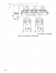
Use
this
chart
in
conjunction
with
the
circuit
diagram
while
performing
troubleshooting
procedures.
If
the
trouble
is
not
remedied
after
performing
these
pro
cedures,
the
nearest
Factory
Authorized
Service
Sta
tion
should be
contacted.
In
all
cases
of
equipment
malfunction,
the
manufacturers
recommendations
should
be
strictly
followed.
I~
I
Hazardous
voltages
are
present
on
the
in
ternal
circuitry
of
the
welding
power
source
as
long
as
power
is
connected
to
the
unit.
Disconnect
power
before
attempting
any
inspection
or
work
on
the
inside
of
the
unit.
Troubleshooting
of
internal
circuitry
should
be
performed
by
qualified
personnel
only.
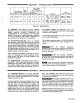
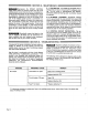
The
following
chart
is
designed
to
diagnose
and
provide
remedies
for
some
of
the
troubles
that
may
develop
in
this
welding
power
source.
TROUBLE
PROBABLE
CAUSE
REMEDY
No
output.
Thermostat
TP1
open.
Allow
unit
a
cooling
period.
Replace
defective
TP1.
Circuit
breaker
CB
open.
Reset
CB.
Replace
defective
CB.
Fuse
Fl
is
blown.
*Replace
defective
Fl.
*lf
it
becomes
necessary
to
replace
any
fuse
in
the
welding
power
source,
ensure
that
a
fuse
of
the
proper
size,
type,
and
rating
is
used.
CAUTION:
Depressing
the
POWER
CONTROL
STOP
button
does
not
remove
power
from
all
of
the
welding
power
source
internal
circuitry.
Completely
ter
minate
all
electrical
power
to
the
welding
power
source
by
employing
machinery
lockout
procedures
before
attempting
any
inspection
or
work
on
the
inside
of
the
unit.
If
the
welding
power
source
is
connected
to
a
disconnect
switch,
padlock
the
switch
in
an
open
posi
tion.
If
connected
to
a
fuse
box,
remove
the
fuses
and
padlock
the
cover
in
the
closed
position.
If
the
unit
is
connected
to
a
circuit
breaker,
or
other
disconnecting
device
without
locking
facilities,
attach
a
red
tag
to
the
device
to
warn
others
that
the
circuit
is
being
worked
on.
IMPORTANT:
5-1.
FAN
MOTOR
-
All
models
are
equipped
with
an
exhaust
fan
and
rely
on
forced
draft
for
adequate
cool
ing.
The
fan
motor
is
manufactured
with
lifetime-
lubricated
sealed
ball
bearings
and
no
attention
should
be
required.
5-2.
INTERNAL
CLEANING
-
Occasional
blowing
out
or
vacuuming
of
the
dust
and
dirt
from
around
the
internal
components
is
recommended.
This
should
be
done
periodically
depending
upon
the
location
of
the
unit
and
the
amount
of
dust
and
dirt
in
the
atmosphere.
The
welding
power
source
outer
enclosure
should
be
removed
and
a
clean,
dry
air
stream
or
vacuum
suction
should
be used
for
this
cleaning
operation.
5-3.
CONTROL
CIRCUIT
PROTECTION
-
The
en
tire
control
circuit
of
the
welding
power
source
is
pro
tected
by
a
600
volt,
3
ampere,
cartridge
type
fuse
Fl.
This fuse
is
located
under
the
top
cover
beside
contac
tor
W.
Should
this
fuse
open,
the
welding
power
soure
would
completely
shut
down.
Periodically
inspect
the
labels
on
this
unit
for
legibility.
All
labels
must
be
maintained
in
a
clearly
readable
state
and
replaced
when
necessary.
See
the
Parts
List
for
part
number
of
labels.
p
Page
10