OM-219 316C 2006−10 Processes MIG (GMAW) Welding ® Flux Cored (FCAW) Welding Description Arc Welding Power Source And Wire Feeder MW 140 Plus And H-10 Gun For Warranty Claims And Technical Support, Contact: Milweld Inc., National Distributor P.O.
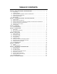
TABLE OF CONTENTS SECTION 1 − SAFETY PRECAUTIONS - READ BEFORE USING . . . . . . . . . . . . . . . . . . . . . . . . . . . . . . . . . . . 1-1. Symbol Usage . . . . . . . . . . . . . . . . . . . . . . . . . . . . . . . . . . . . . . . . . . . . . . . . . . . . . . . . . . . . . . . . . . . . . . . . 1-2. Arc Welding Hazards . . . . . . . . . . . . . . . . . . . . . . . . . . . . . . . . . . . . . . . . . . . . . . . . . . . . . . . . . . . . . . . . . . 1-3.
TABLE OF CONTENTS SECTION 9 − MIG WELDING (GMAW) GUIDELINES . . . . . . . . . . . . . . . . . . . . . . . . . . . . . . . . . . . . . . . . . . . . . . 9-1. Typical MIG Process Connections . . . . . . . . . . . . . . . . . . . . . . . . . . . . . . . . . . . . . . . . . . . . . . . . . . . . . . . 9-2. Typical MIG Process Control Settings . . . . . . . . . . . . . . . . . . . . . . . . . . . . . . . . . . . . . . . . . . . . . . . . . . . . 9-3. Holding And Positioning Welding Gun . . . . . . . . . . . . .
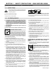
SECTION 1 − SAFETY PRECAUTIONS - READ BEFORE USING som _3/05 Y Warning: Protect yourself and others from injury — read and follow these precautions. 1-1. Symbol Usage Means Warning! Watch Out! There are possible hazards with this procedure! The possible hazards are shown in the adjoining symbols. Y Marks a special safety message. . Means “Note”; not safety related. This group of symbols means Warning! Watch Out! possible ELECTRIC SHOCK, MOVING PARTS, and HOT PARTS hazards.
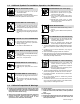
ARC RAYS can burn eyes and skin. Arc rays from the welding process produce intense visible and invisible (ultraviolet and infrared) rays that can burn eyes and skin. Sparks fly off from the weld. D Wear an approved welding helmet fitted with a proper shade of filter lenses to protect your face and eyes when welding or watching (see ANSI Z49.1 and Z87.1 listed in Safety Standards). D Wear approved safety glasses with side shields under your helmet.
1-3. Additional Symbols For Installation, Operation, And Maintenance FIRE OR EXPLOSION hazard. MOVING PARTS can cause injury. D Do not install or place unit on, over, or near combustible surfaces. D Do not install unit near flammables. D Do not overload building wiring − be sure power supply system is properly sized, rated, and protected to handle this unit. D Keep away from moving parts such as fans. D Keep all doors, panels, covers, and guards closed and securely in place.
1-5. Principal Safety Standards Safety in Welding, Cutting, and Allied Processes, ANSI Standard Z49.1, from Global Engineering Documents (phone: 1-877-413-5184, website: www.global.ihs.com). Boulevard, Rexdale, Ontario, Canada M9W 1R3 (phone: 800−463−6727 or in Toronto 416−747−4044, website: www.csa−international.org). Recommended Safe Practices for the Preparation for Welding and Cutting of Containers and Piping, American Welding Society Standard AWS F4.
SECTION 2 − CONSIGNES DE SÉCURITÉ − LIRE AVANT UTILISATION fre_som _3/05 Y Avertissement : se protéger et protéger les autres contre le risque de blessure — lire et respecter ces consignes. 2-1. Symboles utilisés Symbole graphique d’avertissement ! Attention ! Cette procédure comporte des risques possibles ! Les dangers éventuels sont représentés par les symboles graphiques joints. Y Indique un message de sécurité particulier . Signifie NOTE ; n’est pas relatif à la sécurité. 2-2.
LES RAYONS D’ARC peuvent entraîner des brûlures aux yeux et à la peau. Le rayonnement de l’arc du procédé de soudage génère des rayons visibles et invisibles intenses (ultraviolets et infrarouges) susceptibles de provoquer des brûlures dans les yeux et sur la peau. Des étincelles sont projetées pendant le soudage. D Porter un casque de soudage approuvé muni de verres filtrants approprié pour protéger visage et yeux pendant le soudage (voir ANSI Z49.1 et Z87.1 énuméré dans les normes de sécurité).
2-3. Dangers supplémentaires en relation avec l’installation, le fonctionnement et la maintenance Risque D’INCENDIE OU D’EXPLOSION. DES ORGANES MOBILES peuvent provoquer des blessures. D Ne pas placer l’appareil sur, au-dessus ou à proximité de surfaces inflammables. D Ne pas installer l’appareil à proximité de produits inflammables. D Ne pas surcharger l’installation électrique − s’assurer que l’alimentation est correctement dimensionnée et protégée avant de mettre l’appareil en service.
2-5. Principales normes de sécurité Safety in Welding, Cutting, and Allied Processes, ANSI Standard Z49.1, de Global Engineering Documents (téléphone : 1-877-413-5184, site Internet : www.global.ihs.com). Boulevard, Rexdale, Ontario, Canada M9W 1R3 (téléphone : 800-463-6727 ou à Toronto 416-747-4044, site Internet : www.csa-international.org). Recommended Safe Practices for the Preparation for Welding and Cutting of Containers and Piping, American Welding Society Standard AWS F4.
SECTION 3 − DEFINITIONS 3-1. Symbols And Definitions A V Amperage Hz Voltage Hertz Negative Positive Direct Current (DC) Single Phase Input Output Voltage Input Off On Do Not Switch While Welding Gas Metal Arc Welding (GMAW) Wire Feed SECTION 4 − SPECIFICATIONS 4-1.
4-2. Duty Cycle And Overheating Duty Cycle is percentage of 10 minutes that unit can weld at rated load without overheating. If unit overheats, thermostat(s) opens, output stops, and cooling fan runs. Wait fifteen minutes for unit to cool. Reduce amperage or duty cycle before welding. 200 Output Amperes 140 Y Exceeding duty cycle can damage unit or gun and void warranty.
4-3. Volt-Ampere Curves The volt-ampere curves show the minimum and maximum voltage and amperage output capabilities of the welding power source. Curves of other settings fall between the curves shown. 30.0 25.0 20.0 Voltage RANGE4 15.0 RANGE3 RANGE2 RANGE1 10.0 5.0 0.0 0 10 20 30 40 50 60 70 80 90 100 110 Amperage 120 130 140 150 160 ssb1.
SECTION 5 − INSTALLATION 5-1. Installing Welding Gun 1 2 3 4 Drive Assembly Gun Securing Thumbscrew Gun End Loosen thumbscrew. Insert end through opening until it bottoms against drive assembly. Tighten thumbscrew. 3 Welding gun must be inserted completely to prevent leakage of shielding gas. 4 1 2 Close door. . Be sure that gun end is tight against drive assembly. 3 Incorrect Gun Not Seated Gun Trigger Leads Insert leads, one at a time, through gun opening on front panel.
5-3. Process/Polarity Table Process Cable Connections Polarity Cable To Gun Cable To Work GMAW − Solid wire with shielding gas DCEP − Reverse polarity Connect to positive (+) output terminal Connect to negative (−) output terminal FCAW − Self-shielding wire − no shielding gas DCEN − Straight Polarity Connect to negative (−) output terminal Connect to positive (+) output terminal 5-4.
5-5. Installing Gas Supply Obtain gas cylinder and chain to running gear, wall, or other stationary support so cylinder cannot fall and break off valve. . DO NOT use Argon/Mixed gas regulator/flowmeter with CO2 shielding gas. See Parts List for optional CO2 gas regulator/flowmeter. 1 1 Cap 2 Cylinder Valve Remove cap, stand to side of valve, and open valve slightly. Gas flow blows dust and dirt from valve. Close valve. 4 2 7 3 3 Cylinder 4 Regulator/Flowmeter Install so face is vertical.
5-6. Selecting A Location And Connecting Input Power 1 2 Rating Label Grounded Receptacle A 115 volt, 20 ampere individual branch circuit protected by time-delay fuses or circuit breaker is required. 3 Plug From Unit Select extension cord of 14 AWG for up to 50 ft (15 m) or 12 AWG for 50 up to 200 ft (61 m). Y Special installation may be required where gasoline or volatile liquids are present − see NEC Article 511 or CEC Section 20. Y Do not move or operate unit where it could tip.
5-7. Installing Wire Spool And Adjusting Hub Tension Installing 4 in (102 mm) Wire Spool When a slight force is needed to turn spool, tension is set. Installing 8 in (203 mm) Wire Spool Adapter used with 8 in (203 mm) spool only. When a slight force is needed to turn spool, tension is set. Retaining ring used with 8 in (203 mm) spool only. Tools Needed: 1/2 in 803 012 / 803 013 -B / Ref.
5-8. Installing Contact Tip And Nozzle Y Turn off welding power source. 1 Nozzle Remove nozzle. Contact Tip 3 Tip Adapter Thread welding wire through gun (see Section 5-9). 3 2 Slide contact tip over wire and tighten tip into tip adapter. Install nozzle. 1 Flux Nozzle 2 MIG Nozzle Use with flux cored wire only. Narrow design allows access in tight spaces and provides better visibility of puddle during welding. Use with solid or flux cored wire.
5-9. Threading Welding Wire 1 2 3 4 5 6 4 Wire Spool Welding Wire Inlet Wire Guide Pressure Adjustment Knob Drive Roll Gun Conduit Cable Lay gun cable out straight. 6 Tools Needed: 1 2 3 5 . Hold wire tightly to keep it from unraveling. 4 in (102 mm) 6 in (150 mm) Open pressure assembly. Make sure feed roll is set to correct groove to match wire size (see Section 7-4). Pull and hold wire; cut off end. . Use pressure indicator Tighten scale to set a desired drive roll pressure.
SECTION 6 − OPERATION 6-1. Controls 1 2 NE PAS CHANGER DE PROCÉDÉ 3 Ref. 230 002-A 1 Wire Speed Control Use control to select a wire feed speed. As Voltage switch setting increases, wire speed range also increases (see weld setting label in welding power source or Section 6-2). 2 3 Power Switch Voltage Switch The higher the selected number, the thicker the material that can be welded (see weld setting label in welding power source or Sections 6-2). Do not switch under load. .
6-2.
217 618-A OM-219 316 Page 21
SECTION 7 − MAINTENANCE &TROUBLESHOOTING 7-1. Routine Maintenance Y Disconnect power before maintaining. 3 Months Replace unreadable labels. Repair or replace cracked weld cable. Clean and tighten weld terminals. 6 Months Blow out or vacuum inside. During heavy service, clean monthly. Or 7-2. Overload Protection 1 Supplementary Protector CB1 CB1 protects unit from overload. If CB1 opens, unit shuts down. 1 Reset supplementary protector. 802 441 7-3.
7-4. Changing Drive Roll Or Wire Inlet Guide 1 2 Loosen screw. Slide tip as close to drive rolls as possible without touching. Tighten screw. 1 3 3 2 Tools Needed: Inlet Wire Guide Securing Screw Inlet Wire Guide .030/.035 Groove Stamped .024 The drive roll consists of two different sized grooves. The stamped markings on the end surface of the drive roll refers to the groove on the opposite side of the drive roll.
7-6. Cleaning Or Replacing Gun Liner Tools Needed: Y Disconnect gun from unit. 8 mm / 10mm Head Tube Remove nozzle, contact tip, adapter, gas diffuser, and wire outlet guide. 8 mm 10 mm Remove liner. To Reassemble Gun: Insert new liner. Lay gun cable out straight before installing new liner. Blow out gun casing. Install wire outlet guide so that 1/8 in (3 mm) of liner sticks out. Hand tighten outlet guide, and then tighten two full turns more.
7-7. Replacing Switch And/Or Head Tube Y Turn Off welding power source /wire feeder and disconnect gun. 1 Remove handle locking nut. 3 2 Slide handle. Remove switch housing. Install new switch and connect leads (polarity is not important). Reassemble in reverse order. If replacing head tube, continue to end of figure. 4 Secure head tube in vice. 5 6 Loosen jam nut. Remove from vice and turn head tube out by hand. Hand-tighten head tube into cable connector.
7-8. Troubleshooting Table Trouble Remedy No weld output; wire does not feed; fan Secure power cord plug in receptacle (see Section 5-6). does not run run. Replace building line fuse or reset circuit breaker if open. Place Power switch in On position (see Section 6-1). Reset welding power source supplementary protector (see Section 7-2). No weld output; wire does not feed; fan Thermostat TP1 open (overheating).
SECTION 8 − ELECTRICAL DIAGRAM 230 952-A Figure 8-1.
SECTION 9 − MIG WELDING (GMAW) GUIDELINES 9-1. Typical MIG Process Connections Y Weld current can damage electronic parts in vehicles. Disconnect both battery cables before welding on a vehicle. Place work clamp as close to the weld as possible. Regulator/ Flowmeter Wire Feeder/ Power Source Shielding Gas Gas Hose Gun Work Clamp Workpiece light mig 5/97 / Ref.
9-2. Typical MIG Process Control Settings NOTE These settings are guidelines only. Material and wire type, joint design, fitup, position, shielding gas, etc. affect settings. Test welds to be sure they comply to specifications. Material thickness determines weld parameters. 1/8 or 0.125 in Convert Material Thickness to Amperage (A) (0.001 in = 1 ampere) 0.125 in = 125 A .035 in Wire Size Wire Size Amperage Range 0.023 in 30 − 90 A 0.030 in 40 − 145 A 0.
9-3. Holding And Positioning Welding Gun NOTE Welding wire is energized when gun trigger is pressed. Before lowering helmet and pressing trigger, be sure wire is no more than 1/2 in (13 mm) past end of nozzle, and tip of wire is positioned correctly on seam.
9-4. Conditions That Affect Weld Bead Shape NOTE Weld bead shape depends on gun angle, direction of travel, electrode extension (stickout), travel speed, thickness of base metal, wire feed speed (weld current), and voltage.
9-5. Gun Movement During Welding NOTE Normally, a single stringer bead is satisfactory for most narrow groove weld joints; however, for wide groove weld joints or bridging across gaps, a weave bead or multiple stringer beads works better. 1 1 2 2 3 Stringer Bead − Steady Movement Along Seam Weave Bead − Side To Side Movement Along Seam Weave Patterns Use weave patterns to cover a wide area in one pass of the electrode. 3 S-0054-A 9-6.
9-8. Troubleshooting − Excessive Spatter Excessive Spatter − scattering of molten metal particles that cool to solid form near weld bead. S-0636 Possible Causes Corrective Actions Wire feed speed too high. Select lower wire feed speed. Voltage too high. Select lower voltage range. Electrode extension (stickout) too long. Use shorter electrode extension (stickout). Workpiece dirty. Remove all grease, oil, moisture, rust, paint, undercoating, and dirt from work surface before welding.
9-11. Troubleshooting − Lack Of Penetration Lack Of Penetration − shallow fusion between weld metal and base metal. Lack of Penetration Good Penetration S-0638 Possible Causes Corrective Actions Improper joint preparation. Material too thick. Joint preparation and design must provide access to bottom of groove while maintaining proper welding wire extension and arc characteristics. Improper weld technique. Maintain normal gun angle of 0 to 15 degrees to achieve maximum penetration.
9-14. Troubleshooting − Waviness Of Bead Waviness Of Bead − weld metal that is not parallel and does not cover joint formed by base metal. S-0641 Possible Causes Corrective Actions Welding wire extends too far out of nozzle. Be sure welding wire extends not more than 1/2 in (13 mm) beyond nozzle. Unsteady hand. Support hand on solid surface or use two hands. 9-15. Troubleshooting − Distortion Distortion − contraction of weld metal during welding that forces base metal to move.
9-16. Common MIG Shielding Gases This is a general chart for common gases and where they are used. Many different combinations (mixtures) of shielding gases have been developed over the years. The most commonly used shielding gases are listed in the following table.
Problem Probable Cause Remedy Welding arc not stable. Wire slipping in drive rolls. Adjust pressure setting on wire feed rolls. Replace worn drive rolls if necessary. Wrong size gun liner or contact tip. Match liner and contact tip to wire size and type. Incorrect voltage setting for selected wire feed speed on Readjust welding parameters. welding power source. Loose connections at the gun weld cable or work cable. Check and tighten all connections. Gun in poor shape or loose connection inside gun.
SECTION 10 − PARTS LIST 22 . Hardware is common and 24 36 31 40 54 42 41 44 46 45 51 50 47 1 43 48 38 33 39 30 32 2 49 37 34 35 3 4 29 5 6 7 8 28 9 52 10 11 27 12 13 26 25 17 23 16 19 15 14 18 20 21 53 not available unless listed. 803 716-B Figure 10-1.
Item No. Dia. Mkgs. Part No. Description Quantity Figure 10-1. Main Assembly ... ... ... ... ... ... ... ... ... ... ... ... ... ... ... ... ... ... ... ... ... ... ... ... ... ... ... ... ... ... ... ... ... ... ... ... ... ... ... ... 1 2 3 4 5 6 7 8 9 10 11 12 13 14 15 16 17 18 19 20 21 22 23 24 25 26 27 28 29 30 31 32 33 34 35 36 37 38 39 40 . . . . . . . . . . . . . . . 199 566 . . . . . . . . . . . . . . . 196 006 . . . . . . . . . . . . . . . 211 887 . . . . . . . . . . . . . . . 204 608 . . .
Item No. Dia. Mkgs. Part No. Description Quantity Figure 10-1. Main Assembly (Continued) ... ... ... ... ... ... ... ... ... ... ... ... ... ... ... 41 42 43 44 45 46 47 48 49 50 50 51 52 53 54 . . . . . . . . . . . . . . . 207 079 . . KNOB, pointer (voltage) . . . . . . . . . . . . . . . . . . . . . . . . . . . . . . . . . . . . . . . . . . . . . . . . . . . . . . . . 211 338 . . KNOB, pointer (WFS) . . . . . . . . . . . . . . . . . . . . . . . . . . . . . . . . . . . . . . . . . . . . . . . . . . .
1 3 2 4 5 6 7 9 8 11 10 802 447 Figure 10-2. H-10 Gun Item No. Part No. 195 957 ... ... ... ... ... ... ... ... ... ... ... ... ... ... ... ... ... ... 1 1 2 2 2 2 3 4 5 6 7 8 9 9 9 9 10 11 . . . . . . . . . . . . . . . 169 715 . . . . . . . . . . . . . ♦226 190 . . . . . . . . . . . . . ♦087 299 . . . . . . . . . . . . . ♦000 067 . . . . . . . . . . . . . ♦000 068 . . . . . . . . . . . . . ♦000 069 . . . . . . . . . . . . . . . 169 716 . . . . . . . . . . . . . . . 170 470 . . . . . . . . . .
10-3. Optional Drive Rolls For All Feed Head Assemblies PART NO. WIRE DIAMETER INCHES (mm) 202 925 .023/.025 (.6) and .030/.035 (.8 and .9) 202 926 .030/.035 (.8 and .9) and .045 (1.2 VK Groove) 10-4. Options PART NO. DESCRIPTION REMARKS 770 187 Running Gear/Cylinder Rack For One Small Gas Cylinder, 100 lb (45 kg) max. 194 776 Small Running Gear/Cylinder Rack For One Small Gas Cylinder, 75 lb (34 kg) max.
Warranty Effective January 1, 2006 (Equipment with a serial number preface of “LG” or newer) * This limited warranty supersedes all previous manufacturers warranties and is exclusive with no other guarantees or warranties expressed or implied. LIMITED WARRANTY − Subject to the terms and conditions below, warrants to its original retail purchaser that new equipment sold after the effective date of this limited warranty is free of defects in material and workmanship at the time it is shipped from factory.
Owner’s Record Please complete and retain with your personal records. Model Name Serial/Style Number Purchase Date (Date which equipment was delivered to original customer.) Distributor Address City State Zip Resources Available Always provide Model Name and Serial/Style Number.