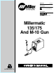
OM-1324 204 408C April 2003 Processes MIG (GMAW) Welding Flux Cored (FCAW) Welding Description Arc Welding Power Source And Wire Feeder Millermatic 135/175 And M-10 Gun R Visit our website at www.MillerWelds.
From Miller to You Thank you and congratulations on choosing Miller. Now you can get the job done and get it done right. We know you don’t have time to do it any other way. That’s why when Niels Miller first started building arc welders in 1929, he made sure his products offered long-lasting value and superior quality. Like you, his customers couldn’t afford anything less. Miller products had to be more than the best they could be. They had to be the best you could buy.
TABLE OF CONTENTS WARNING This product, when used for welding or cutting, produces fumes or gases which contain chemicals known to the State of California to cause birth defects and, in some cases, cancer. (California Health & Safety Code Section 25249.5 et seq.) The following terms are used interchangeably throughout this manual: MIG=GMAW OM-1324 SECTION 1 – SAFETY PRECAUTIONS - READ BEFORE USING . . . . . . . . . . . . . . . . . . . . . . . . . . . . 1-1. Symbol Usage . . . . . . . . . . . . . . . . .
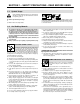
SECTION 1 – SAFETY PRECAUTIONS - READ BEFORE USING som _nd_4/98 1-1. Symbol Usage Means Warning! Watch Out! There are possible hazards with this procedure! The possible hazards are shown in the adjoining symbols. Y Marks a special safety message. . Means “Note”; not safety related. This group of symbols means Warning! Watch Out! possible ELECTRIC SHOCK, MOVING PARTS, and HOT PARTS hazards. Consult symbols and related instructions below for necessary actions to avoid the hazards. 1-2.
ARC RAYS can burn eyes and skin. Arc rays from the welding process produce intense visible and invisible (ultraviolet and infrared) rays that can burn eyes and skin. Sparks fly off from the weld. D Wear a welding helmet fitted with a proper shade of filter to protect your face and eyes when welding or watching (see ANSI Z49.1 and Z87.1 listed in Safety Standards). D Wear approved safety glasses with side shields under your helmet.
1-3. Additional Symbols For Installation, Operation, And Maintenance FIRE OR EXPLOSION hazard. MOVING PARTS can cause injury. D Do not install or place unit on, over, or near combustible surfaces. D Do not install unit near flammables. D Do not overload building wiring – be sure power supply system is properly sized, rated, and protected to handle this unit. D Keep away from moving parts such as fans. D Keep all doors, panels, covers, and guards closed and securely in place.
1-5. EMF Information Considerations About Welding And The Effects Of Low Frequency Electric And Magnetic Fields Welding current, as it flows through welding cables, will cause electromagnetic fields. There has been and still is some concern about such fields.
SECTION 1 – CONSIGNES DE SECURITE – LIRE AVANT UTILISATION som _nd_fre 4/98 1-1. Signification des symboles Signifie Mise en garde ! Soyez vigilant ! Cette procédure présente des risques de danger ! Ceux-ci sont identifiés par des symboles adjacents aux directives. Y Identifie un message de sécurité particulier. . Signifie NOTA ; n’est pas relatif à la sécurité.
LES RAYONS DE L’ARC peuvent provoquer des brûlures dans les yeux et sur la peau. Le rayonnement de l’arc du procédé de soudage génère des rayons visibles et invisibles intenses (ultraviolets et infrarouges) susceptibles de provoquer des brûlures dans les yeux et sur la peau. Des étincelles sont projetées pendant le soudage. D Porter un casque de soudage muni d’un écran de filtre approprié pour protéger votre visage et vos yeux pendant le soudage ou pour regarder (voir ANSI Z49.1 et Z87.
1-3. Dangers supplémentaires en relation avec l’installation, le fonctionnement et la maintenance Risque D’INCENDIE OU D’EXPLOSION. DES ORGANES MOBILES peuvent provoquer des blessures. D Ne pas placer l’appareil sur, au-dessus ou à proximité de surfaces infllammables. D Rester à l’écart des organes mobiles comme le ventilateur. D Maintenir fermés et fixement en place les portes, panneaux, recouvrements et dispositifs de protection.
1-4. Principales normes de sécurité Safety in Welding and Cutting, norme ANSI Z49.1, de l’American Welding Society, 550 N.W. Lejeune Rd, Miami FL 33126 Safety and Health Sandards, OSHA 29 CFR 1910, du Superintendent of Documents, U.S. Government Printing Office, Washington, D.C. 20402. Recommended Safe Practice for the Preparation for Welding and Cutting of Containers That Have Held Hazardous Substances, norme AWS F4.1, de l’American Welding Society, 550 N.W.
SECTION 2 – SPECIFICATIONS 2-1. Specifications A. 115 VAC Model Rated Welding Output Maximum Open-Circuit Voltage DC Amperage Range KVA KW Weight W/ Gun Overall Dimensions Length: 17-1/2 in (444 mm) 90 A @ 18 Volts DC, 20% Duty Cycle 30 – 135 20 2.88 2.40 15* 2.20* 1.77* 28 63 A @ 21 Volts DC, 20% Duty Cycle* 60 lb (27 kg) Width: 10-5/8 in (273 mm) Height: 15-3/4 in (400 mm) Solid Wire Type And Dia Amperes Input at Rated Load Output 115 V, 60 Hz, Single-Phase Stainless .024 - .
2-2. Duty Cycle And Overheating 140 Duty Cycle is percentage of 10 minutes that unit can weld at rated load without overheating. 120 Output Amperes A. 115 VAC Model 100 If unit overheats, thermostat(s) opens, output stops, and cooling fan runs. Wait fifteen minutes for unit to cool. Reduce amperage or duty cycle before welding. RatedOutput 80 Y Exceeding duty cycle can damage unit or gun and void warranty.
2-3. Volt-Ampere Curves The volt-ampere curves show the minimum and maximum voltage and amperage output capabilities of the welding power source. Curves of other settings fall between the curves shown. A. 115 VAC Model 30 25 VOLTAGE 20 Voltage Control @ 0 Voltage Control @ 1 Voltage Control @ 2 Voltage Control @ 3 Voltage Control @ 4 Voltage Control @ 5 Voltage Control @ 6 Voltage Control @ 7 Voltage Control @ 8 Voltage Control @ 9 Voltage Control @ 10 15 10 5 0 0.0 10.0 20.0 30.0 40.0 50.0 60.
SECTION 3 – INSTALLATION 3-1. Installing Welding Gun 1 2 3 Drive Assembly Gun Securing Knob Gun End Loosen knob. Insert gun end through opening until it bottoms against drive assembly. Tighten knob. 4 Gun Trigger Plug Insert into receptacle, and tighten threaded collar. 3 1 4 Close door. 2 Ref. 802 982 / Ref. 801 987 3-2. Installing Work Clamp 1 2 3 4 5 3 1 2 Nut Work Cable From Unit Work Clamp Screw Work Clamp Tabs Bend tabs around work cable. Tools Needed: 4 5 3/8, 7/16 in 802 456 3-3.
3-4. Process/Polarity Table Cable Connections Process Polarity Cable To Gun Cable To Work GMAW – Solid wire with shielding gas DCEP – Reverse polarity Connect to positive (+) output terminal Connect to negative (–) output terminal FCAW – Self-shielding wire – no shielding gas DCEN – Straight Polarity Connect to negative (–) output terminal Connect to positive (+) output terminal 3-5.
3-6. Installing Gas Supply Obtain gas cylinder and chain to running gear, wall, or other stationary support so cylinder cannot fall and break off valve. Tools Needed: 5/8, 1-1/8 in Cap 2 Cylinder Valve Remove cap, stand to side of valve, and open valve slightly. Gas flow blows dust and dirt from valve. Close valve. 1 2 3 Cylinder 4 Regulator/Flowmeter Install so face is vertical.
3-7. Selecting A Location And Connecting Input Power For 115 VAC Model 1 2 2 1 Rating Label Grounded Receptacle A 115 volt, 20 ampere individual branch circuit protected by time-delay fuses or circuit breaker is required. 18 in (460 mm) 3 3 Plug From Unit Select extension cord of 14 AWG for up to 50 ft (15 m) or 12 AWG for 50 up to 200 ft (61 m). Y Special installation may be required where gasoline or volatile liquids are present – see NEC Article 511 or CEC Section 20. 18 in (460 mm) Ref.
3-8. Selecting A Location And Connecting Input Power For 230 VAC Model 1 Rating Label Supply correct input power. 2 3 Plug Receptacle Connect plug to receptacle. 4 4 18 in (457 mm) of space for airflow Line Disconnect Device See Section 3-9. Y Special installation may be required where gasoline or volatile liquids are present – see NEC Article 511 or CEC Section 20. L1 L2 Y Always connect grounding conductor first.
3-9. Electrical Service Guide For 230 VAC Model Input Voltage 230 Input Amperes At Rated Output 20 Max Recommended Standard Fuse Or Circuit Breaker Rating In Amperes 20 Min Input Conductor Size In AWG/Kcmil 14 Max Recommended Input Conductor Length In Feet (Meters) 66 (20) Min Grounding Conductor Size In AWG/Kcmil 12 Reference: 1996 National Electrical Code (NEC) S-0092-J 3-10.
3-11. Threading Welding Wire 1 2 3 4 5 6 Wire Spool Welding Wire Inlet Wire Guide Pressure Adjustment Knob Drive Roll Gun Conduit Cable Lay gun cable out straight. 4 6 Tools Needed: 1 2 3 5 . Hold wire tightly to keep it from unraveling. 4 in (102 mm) 6 in (150 mm) Open pressure assembly. Pull and hold wire; cut off end. Push wire thru guides into gun; continue to hold wire. . Use pressure indicator scale to set a desired drive roll pressure. Begin with a setting of 3.
SECTION 4 – OPERATION 4-1. Controls 1 2 WIRESPEED V VOLTAGE ON 3 OFF TRIGGER OVERTEMP POWER 4 5 1 Wire Speed Control Turn control clockwise to increase wire feed speed. (see weld parameter chart in welding power source or Sections 4-2 and 4-3, as applicable). 2 Voltage Control Turn control clockwise to increase voltage (see weld parameter chart in welding power source or Sections 4-2 and 4-3, as applicable). 3 Power Switch 4 Over Temperature Light 5 Gun Trigger Receptacle Ref.
4-2. Weld Parameter Chart For 115 VAC Model Selecting Note: Wire, Gas and Control 1. Settings are approximate. Adjust as required. 2. ”––” Means not recommended. 3. Thicker materials can be welded using proper joint preparation and multiple passes.
Select Voltage Number is Voltage and mm) Speed Based of slash Number Knob Setting. is Wire 1/8” (3.2 mm) 16 (1.6 of Metal on Thickness on left 3/16” (4.8 Wire ga. mm) on right Speed (0.9 Welded of slash Knob 20 Being ga. mm) Setting. 24 (0.8 ga. mm) ––– 10 / 75 4.5 / 60 3 / 45 2 / 40 ––– 10 / 60 4 / 45 3 / 35 2 / 30 ––– 10 / 60 5 / 50 4 / 40 ––– ––– 10 / 40 5 / 30 4 / 25 ––– 10 / 60 6 / 55 2.5 / 45 ––– ––– 6 / 45 2.
4-3. Weld Parameter Chart For 230 VAC Model Selecting Note: Wire, Gas and Control 1. Settings are approximate. Adjust as required. 2. ”––” Means not recommended. 3. Thicker materials can be welded using proper joint preparation and multiple passes.
Select Voltage Number is Voltage 1/4” (6.4 mm) and Wire Speed Based on Thickness on left of slash Number Knob Setting. is Wire 3/16” (4.8 mm) 1/8” (3.2 mm) 16 (1.6 of Metal on right Speed ga. mm) Being Welded of slash Knob 20 (0.9 Setting. ga. mm) 24 (0.8 ga. mm) 10 / 100 6 / 100 4.5 / 85 3.5 / 70 2.5 / 50 1.5 / 40 10 / 75 6 / 70 4.5 / 60 3 / 45 2 / 35 1.5 / 30 10 / 70 6 / 55 4.5 / 50 3 / 40 1.5 / 30 ––– ––– 10 / 75 6.
SECTION 5 – MAINTENANCE &TROUBLESHOOTING 5-1. Routine Maintenance Y Disconnect power before maintaining. 3 Months Replace unreadable labels. Repair or replace cracked weld cable. Clean and tighten weld terminals. 6 Months Blow out or vacuum inside. During heavy service, clean monthly. Or 5-2. Overload Protection 1 Circuit Breaker CB1 CB1 protects unit from overload. If CB1 opens, unit shuts down. 1 Reset breaker. 802 441 5-3. Drive Motor Protection And Tip Saver/Short Circuit Protection A.
5-4. Changing Drive Roll Or Wire Inlet Guide 1 Inlet Wire Guide Remove guide by pressing on barbed area or cutting off one end near housing and pulling it out of hole. Push new guide into hole from rear until it snaps in place. 2 1 2 3 Stamped .024 Retaining Pin To secure drive roll, locate open slot and push drive roll completely over retaining pin, then rotate drive roll 1/4 turn to closed slot. 3 .030/.035 Groove Drive Roll The drive roll consists of two different sized grooves.
5-6. Cleaning Or Replacing Gun Liner Tools Needed: Y Disconnect gun from unit. 8 mm / 10 mm Head Tube Remove nozzle, contact tip, adapter, gas diffuser, and wire outlet guide. 8 mm 10 mm Remove liner. Lay gun cable out straight before installing new liner. To Reassemble Gun: Install and tighten new liner. Blow out gun casing. Cut liner off 3/4 in (20 mm) (3/8 in [9.5 mm] for aluminum) from head tube. Install adapter, contact tip, and nozzle. Ref.
5-7. Replacing Switch And/Or Head Tube Y Turn Off welding power source /wire feeder and disconnect gun. 1 Remove handle locking nut. 3 2 Slide handle. Remove switch housing. Install new switch and connect leads (polarity is not important). Reassemble in reverse order. If replacing head tube, continue to end of figure. 4 Secure head tube in vice. 5 6 Loosen jam nut. Remove from vice and turn head tube out by hand. Hand-tighten head tube into cable connector.
5-8. Troubleshooting Table Trouble Remedy No weld output; wire does not feed; fan Secure power cord plug in receptacle (see Section 3-7). does not run. Replace building line fuse or reset circuit breaker if open. Place Power switch in On position (see Section 4-1). Reset welding power source circuit breaker if open. No weld output; wire does not feed; fan Thermostat TP1 open (overheating). Allow fan to run with gun trigger switch off; thermostat closes when motor continues to run.
SECTION 6 – ELECTRICAL DIAGRAM 203 765 Figure 6-1.
203 794 Figure 6-2.
SECTION 7 – MIG WELDING (GMAW) GUIDELINES 7-1. Typical MIG Process Connections Y Weld current can damage electronic parts in vehicles. Disconnect both battery cables before welding on a vehicle. Place work clamp as close to the weld as possible. Regulator/ Flowmeter Wire Feeder/ Power Source Shielding Gas Gas Hose Gun Work Clamp Workpiece light mig 5/967 / Ref.
7-2. Typical MIG Process Control Settings NOTE These settings are guidelines only. Material and wire type, joint design, fitup, position, shielding gas, etc. affect settings. Test welds to be sure they comply to specifications. Material thickness determines weld parameters. 1/8 or .125 in Convert Material Thickness to Amperage (A) (.001 in = 1 ampere) .125 in = 125 A .035 in Wire Size Amperage Range .023 in 30 – 90 A .030 in .
7-3. Holding And Positioning Welding Gun NOTE Welding wire is energized when gun trigger is pressed. Before lowering helmet and pressing trigger, be sure wire is no more than 1/2 in (13 mm) past end of nozzle, and tip of wire is positioned correctly on seam.
7-4. Conditions That Affect Weld Bead Shape NOTE Weld bead shape depends on gun angle, direction of travel, electrode extension (stickout), travel speed, thickness of base metal, wire feed speed (weld current), and voltage.
7-5. Gun Movement During Welding NOTE Normally, a single stringer bead is satisfactory for most narrow groove weld joints; however, for wide groove weld joints or bridging across gaps, a weave bead or multiple stringer beads works better. 1 1 2 2 3 Stringer Bead – Steady Movement Along Seam Weave Bead – Side To Side Movement Along Seam Weave Patterns Use weave patterns to cover a wide area in one pass of the electrode. 3 S-0054-A 7-6.
7-8. Troubleshooting – Excessive Spatter Excessive Spatter – scattering of molten metal particles that cool to solid form near weld bead. S-0636 Possible Causes Corrective Actions Wire feed speed too high. Select lower wire feed speed. Voltage too high. Select lower voltage range. Electrode extension (stickout) too long. Use shorter electrode extension (stickout). Workpiece dirty. Remove all grease, oil, moisture, rust, paint, undercoating, and dirt from work surface before welding.
7-10. Troubleshooting – Excessive Penetration Excessive Penetration – weld metal melting through base metal and hanging underneath weld. Excessive Penetration Good Penetration S-0639 Possible Causes Excessive heat input. Corrective Actions Select lower voltage range and reduce wire feed speed. Increase travel speed. Wrong polarity. Configure polarity as shown in Section 3-5. Always read and follow wire manufacturer’s recommended polarity, and see Section 3-4. 7-11.
7-13. Troubleshooting – Burn-Through Burn-Through – weld metal melting completely through base metal resulting in holes where no metal remains. S-0640 Possible Causes Corrective Actions Excessive heat input. Select lower voltage range and reduce wire feed speed. Increase and/or maintain steady travel speed. Wrong polarity. Configure polarity as shown in Section 3-5. Always read and follow wire manufacturer’s recommended polarity, and see Section 3-4. 7-14.
7-16. Common MIG Shielding Gases This is a general chart for common gases and where they are used. Many different combinations (mixtures) of shielding gases have been developed over the years. The most commonly used shielding gases are listed in the following table.
22 20 12 13 10 29 33 31 6 25 30 30 42 8 37 36 39 35 43 34 38 4 28 2 5 27 11 26 40 41 7 9 1 14 15 16 23 18 24 17 19 32 21 3 SECTION 8 – PARTS LIST . Hardware is common and not available unless listed. 907 020 Figure 8-1.
Item No. Dia. Mkgs. Part No. Description Quantity Figure 8-1. Main Assembly . . . 1 . . . . . . . . . . . . . . . . . . 202 581 . . . . . . 2 . . . . . . . . . . . . . . . . . . 202 582 . . . . . . 3 . . . . . . . . . . . . . . . . . . 202 583 . . . . . . 4 . . . . . . . . . . . . . . . . . . 202 584 . . . . . . 5 . . . . . . . . . . . . . . . . . . 202 411 . . . . . . . . . . . . . . . . . . . . . . . . . . . 203 498 . . . . . . . . . . . . . . . . . . . . . . . . . . . 203 499 . . . . . . 6 . . . .
Item No. Dia. Mkgs. Part No. Description Quantity Figure 8-1. Main Assembly (Continued) ... ... ... ... ... ... ... ... ... ... ... ... ... ... 31 31 32 33 34 35 36 37 38 39 40 41 42 43 .................. .................. .................. .................. .................. .................. .................. .................. .................. .................. .................. .................. . . . . . TE1 . . . . . . . . .................. 208 267 . . . 208 268 . . . 204 036 . .
203 565 Figure 8-2. Wire Feed Drive Assembly Item No. Dia. Mkgs. Part No. Description Quantity Figure 8-2. Wire Feed Drive Assembly ... ... ... ... ... ... ... ... ... ... ... ... ... ... ... ... ... 1 2 3 4 5 6 7 8 9 10 11 12 13 14 15 16 17 .................. .................. .................. .................. .................. .................. .................. .................. .................. .................. .................. . . . . . DM . . . . . . . . .................. ....
1 3 2 4 5 6 7 10 11 12 8 9 802 388-A Figure 8-3.
Item No. Part No. Description Quantity Figure 8-3. M-10 Gun ... ... ... ... ... ... ... ... ... ... ... ... ... ... ... ... ... 1 2 2 2 2 3 4 5 6 7 8 9 10 10 10 11 12 . . . . . 169 715 . . . ♦087 299 . . . ♦000 067 . . . ♦000 068 . . . ♦000 069 . . . . . 169 716 . . . . . 170 470 . . . . . 169 718 . . . . . 169 738 . . . . . 194 524 . . . . . 180 433 . . . . . 079 974 . . . ♦194 010 . . . ♦194 011 . . . ♦194 012 . . . . . 079 975 . . . . . 196 255 . . NOZZLE, slip type .500 orf flush . . . . . . . .
Notes
Effective January 1, 2002 (Equipment with a serial number preface of “LC” or newer) This limited warranty supersedes all previous Miller warranties and is exclusive with no other guarantees or warranties expressed or implied. Warranty Questions? Call 1-800-4-A-MILLER for your local Miller distributor. Your distributor also gives you ... Service You always get the fast, reliable response you need. Most replacement parts can be in your hands in 24 hours.
Owner’s Record Please complete and retain with your personal records. Model Name Serial/Style Number Purchase Date (Date which equipment was delivered to original customer.) Distributor Address City State Zip For Service Call 1-800-4-A-Miller or see our website at www.MillerWelds.com to locate a DISTRIBUTOR or SERVICE AGENCY near you. Always provide Model Name and Serial/Style Number.