
Operator`s manual


maintenance/
troubleshooting
47
Synrad Firestar t-Series operator’s manual
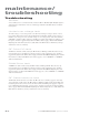
Troubleshooting
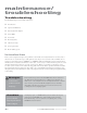
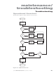
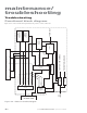
Operational flowchart
The flowchart in Figure 4-1 illustrates Firestar’s start-up sequence.
Ye s
No
INT
(Remote Interlock)
indicator Green?
TMP
(Te mperature)
indicator
Green?
SHT
(Shutter) indicator
Blue?
RDY
(Ready) indicator
Ye llow?
RDY
(Ready) indicator
Ye llow?
Apply interlock signal
to Remote Interlock input
or install factory-supplied
Quick Start Plug
Water-Cooled:
Check that cooling water
is flowing through laser
and that coolant temp
is within specified limits
Apply shutter open
signal to Shutter Open
Request input or install
factory-supplied Quick
Start Plug
Cycle Keyswitch from ON
to OFF and then
back to ON
(on OEM lasers,
cycle DC power)
Ensure that manual
Shutter Switch (if
equipped) is set
to Open
Apply PWM Command
signal to laser
Tu rn Keyswitch
(if equipped)
to ON
Apply DC
power to laser
LASE indicator
illuminates Red to
indicate laser output
Laser Start Sequence
Ye s
Ye s
Ye s
No
No
No
Ye s
No
Air-Cooled:
Check that cooling fans
are clear of debris
and are providing the
specified airflow
Figure 4-1 Operational flowchart